This thread has been locked.
If you have a related question, please click the "Ask a related question" button in the top right corner. The newly created question will be automatically linked to this question.
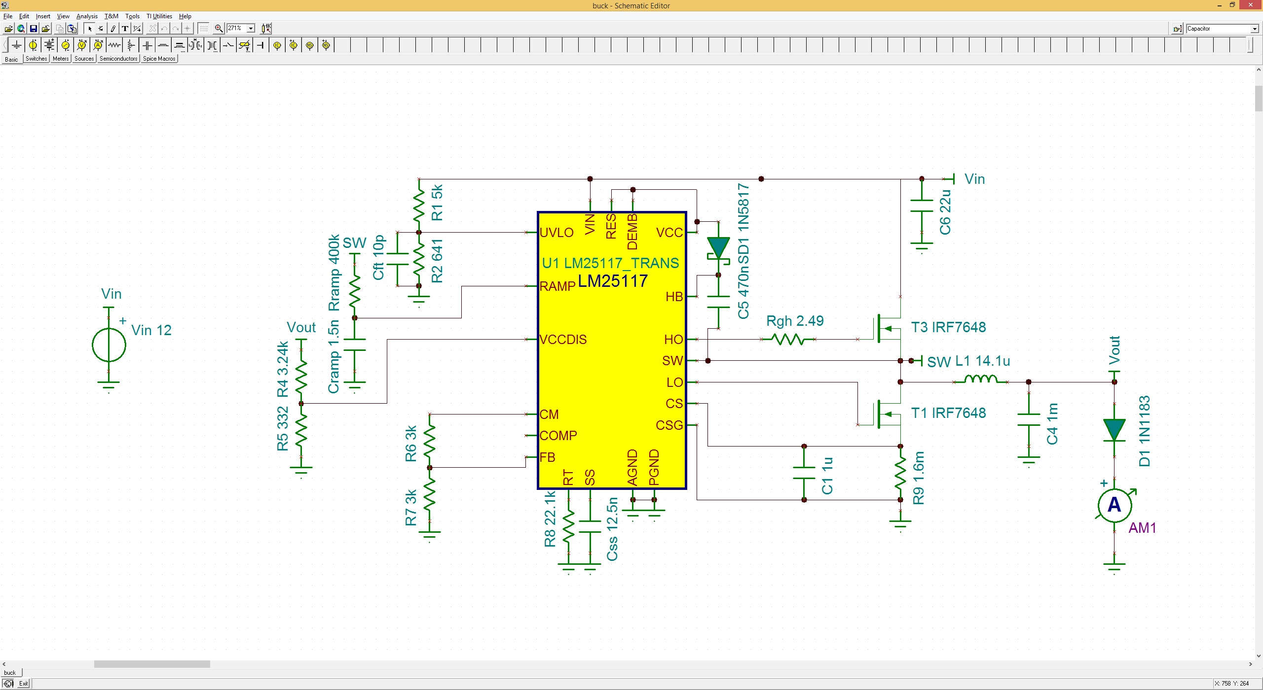
I'm attempting to design a constant current regulator circuit in TINA-TI using the LM25117. The datasheet says that the output voltage of the CM pin should be related to the voltage across CS and CSG (and thus output current). However the simulation results show CM as always being exactly 0V.
My assumption is that the CM pin is simply not modeled in the LM25117 TINA-TI Transient Spice Model. Is this correct?
I see the same issue. I wanted to simulate a circuit where I use the CM output for current regulation, but the viltage output from this pin is just 0 v.
Is this because the CM part i not in the model ? If so is there a newer more which is up-to-date ?
All,
It does appear that the CM pin functionality is not modeled in the current PSpice model. The pin is simply tied to a large resistor and then to ground. The LM5117 model CM pin is also handled in the same fashion.
I do not know of a newer model that would contain the CM functionality.