This thread has been locked.
If you have a related question, please click the "Ask a related question" button in the top right corner. The newly created question will be automatically linked to this question.
Hi,
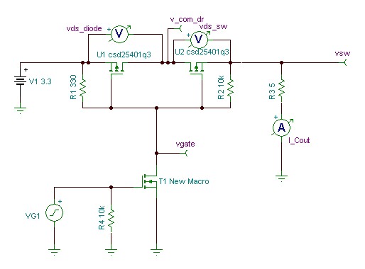
we are trying to simulate circuit which switches 3.3 from input 3.3V by MOSFET. T1 New macro is generated from DMN2005 Spice file.
Derived 3.3V can have maximum load of 1A.
Problems.
1. I can't able to figure how to attach load to the output and simulate., i am not sure attaching 3.3Ohm resistor to load will reasonably simulate the actual load or not?
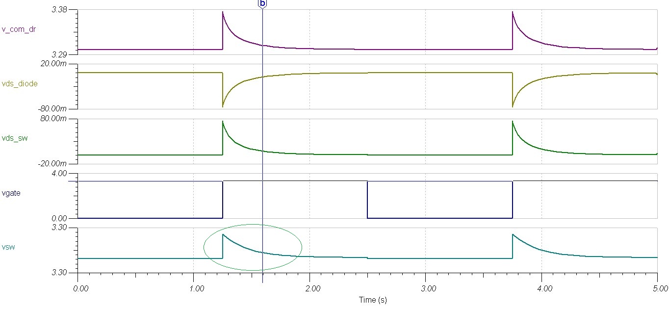
2. I have attached 22uF capacitor at load and Switched 3.3 output is plotted. But, 3.3V is not switching OFF(Captues attached) --Not sure why
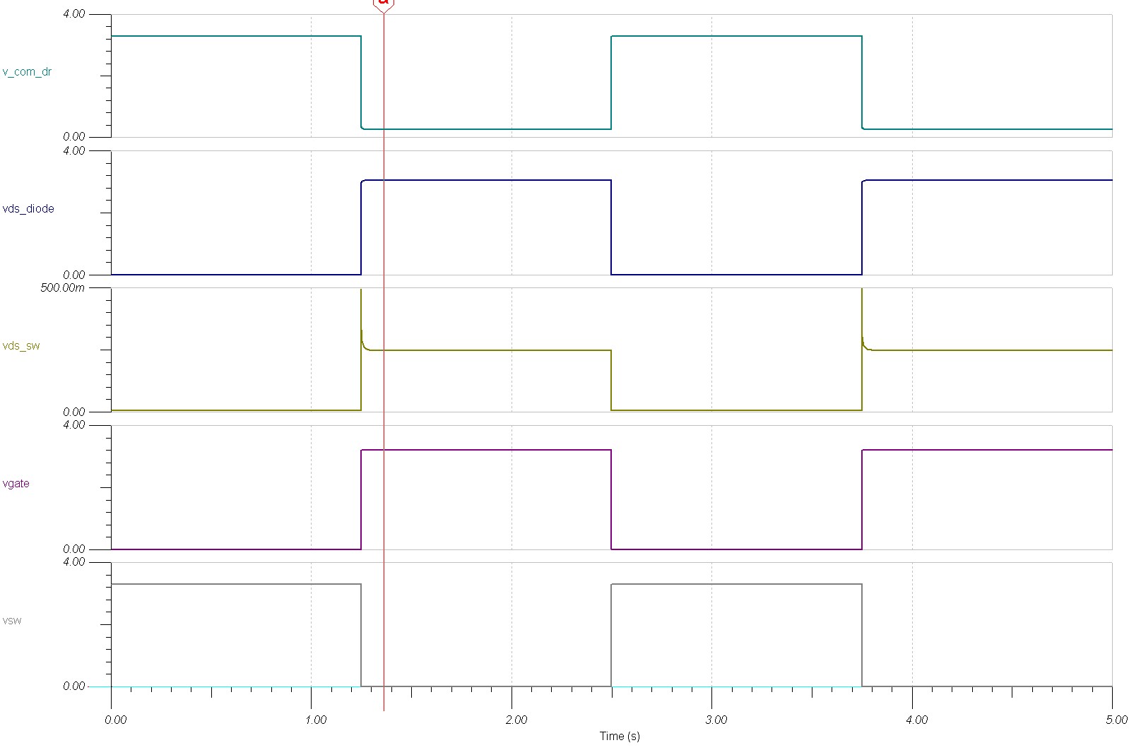
3. In another circuit, i tried with Rload = 6.6Ohms and Cload=22uF, then i can able to get the switched 3.3V properly as per control signal. is this the correct way to simulate load
4. In the Vsw waveform in highted ellipse, if there is a spike in waveform, but if measure voltages with curser it always shows 3.3V, is not showing any voltage chagnes at the spike
Actual circuit contains R1 and R2 as 10K, but with that i am seeing switched 3.3V is not going completely LOW (When Switched OFF, it is going to ~ 1V), So, i changed R1 to 330Ohms. But I am not sure when both are 10k's why exactly ~1v is appearing at switched 3.3V output...
Malli,
What are you really trying to do? The Vgate is switching since you are pulling the gate of the NMOS properly, however, the other two FETs are PMOS devices that you are driving with a positive 3.3V on the gate.
If your are trying to attach a load, a resistor should be fine in parallel with your output capacitor. You can also make the capacitor a little more realistic by adding a series resistance to the capacitor.
Britt
Britt,
Basically it is Load/power rail switch with reverse current protection.
When i have resistive load @ Vsw, i can able to switch Vsw to 3.3V or Zero. But, if i attach only capacitive load Vsw is not going to "0" .
I don't know why?
I think most of the real loads are capacitive -correct me if i wrong. How i can make this circuit to work with capacitive load also.
Malli,
Have you ever tried to hook up a voltage source to a capacitor and measure the current after the capacitor without a load? You will notice that there is no current flowing because there is no path for the current to flow. This is essentially what your are doing with your circuit. When I simulate the circuit provided with a 5 ohm load, I do not get the voltage to drop to 0, I see the voltage drop to near 1V because the current flowing is about 180mA with Vgate=0.
Britt
Hi,
"Have you ever tried to hook up a voltage source to a capacitor and measure the current after the capacitor without a load?"
Current after the capacitor means (There is no other component connected because only voltage source and capacitor) - i didn't get u.
Regarding 5 Ohms load, with 5 Ohms load, i am getting "LOW" on Vsw properly. Here is the circuit and waveforms. For referece i am attaching circuit also.1856.3632.MOSFETSwith2.TSC
Malli,
Please see the attached file:
I have added the capacitive load and changed the VG1 rise/fall time. I also added the current monitor and set up the plots to automatically separate.
Britt