A related question is a question created from another question. When the related question is created, it will be automatically linked to the original question.
If you have a related question, please click the "Ask a related question" button in the top right corner. The newly created question will be automatically linked to this question.
When Run by TINA, the Power Supply should provide 24V. There is no output from it. I tried to use another Voltage source, the DC or AC gives me error. I tried to fix the error but failed.
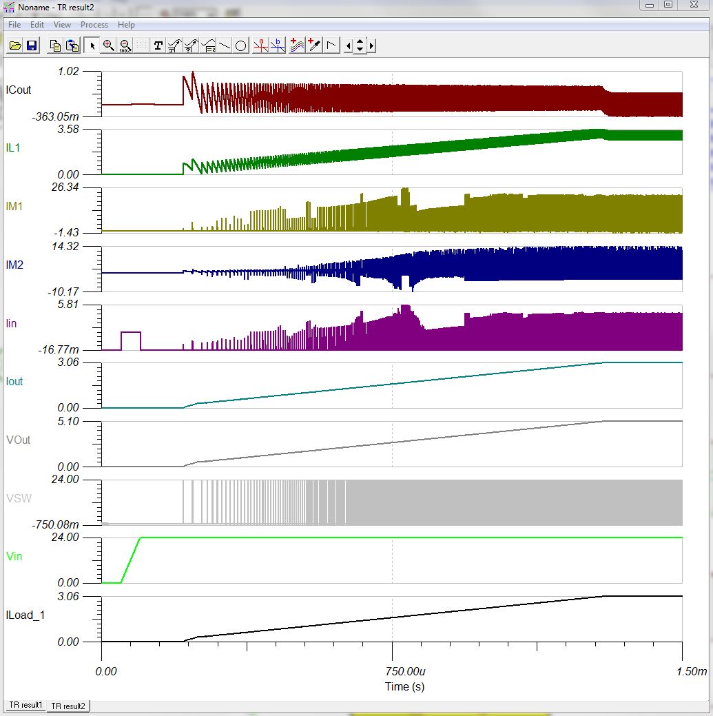
According to your spec your input voltage to the power supply is Vin: 23- 25V, your output voltage is 5V and output current is 3A. I import the TINA file and run the transient analysis for startup and it seems to show the expected result.
Do you expect a different output voltage for this power supply?
This wasn't what I am looking too, I don't need this so I did not check it before.
What I need is to run DC Analysis--> Table of DC results. All values are not logical. I expect it is showing the initial values of the circuit.
Is there a way to show the DC results, or AC result, after a specific time where the circuit voltages is settled. i.e. I need to read e.g. 5V at the output node.
Since the circuit is export for startup simulation so it required to run sometime before it can settle down to a stable output voltage. I think you can try the "Analysis --> Steady Stage Solver" and run the the default value, it will solve all the node and show the voltage and current when the circuit reach steady stage.
The exported .TSC file is functioning correctly. The simulation that was exported is a transient simulation with a transient model. The simulation runs properly if you select Analysis--> Transient you will get the simulation that was requested and exported.
You cannot use the DC analysis on a transient IC model. It will not provide any useful information.
I do not recommend using the Steady State solver either. The transient simulation will provide all of the same information once the simulation is complete. The simulation takes less than a minute to run and provides all of the necessary waveforms to evaluate the design.
The proper way to view the circuit voltages and currents with a transient model is to run a transient analysis. You can look at the values at any specific time point you wish, however, you must run the simulation first. It is a time based simulation.
LM3150 belongs to a type of voltage regulators called switched-mode power supplies. The idea is to deliver power in chunks using a switch, in-between these chunks, an energy storing component (inductor or capacitor) will keep the current flowing through the load.
Due to this nature, you can think of an SMPS as having 2 DC operating points, 1 with the switch turned on and 1 with the switch turned off. If you run a DC analysis, you will get 1 of them.
The other thing to remember is that in this exported design, the input voltage is 0 at time=0. It starts to rise at 50us and reaches 24V at 100us. You DC analysis won't know any of this. It would just take the value at time=0, which is 0. Hence all the nodes in the circuit are practically at 0 per the DC analysis.