This thread has been locked.
If you have a related question, please click the "Ask a related question" button in the top right corner. The newly created question will be automatically linked to this question.
as the title says the model doesn't work as expected
using the reference design provided by the datasheet
http://www.ti.com/lit/ds/symlink/tps62133.pdf\
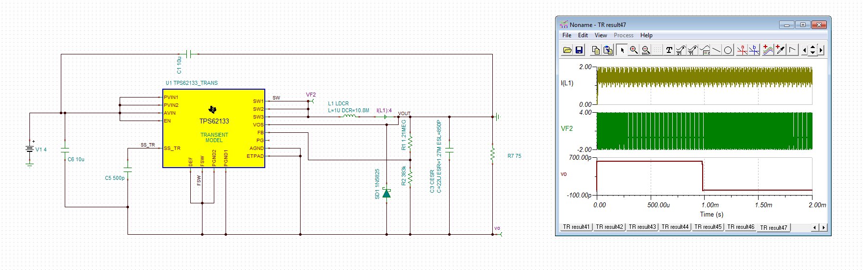
now when running the simulation something quite strange happens, the inverted voltage stays put, it never decreases with time (i know the diode is in an awkward position and that it should go before the inductor in a normal inverting buck boost, just following the reference, if setting the diode before the inductor the device wont switch in the simulation)
something similar happens with the tps54240 (this one in the normal buck-boost configuration) i've built an inverting converter with a tps54240, and it worked as expected
should it be that these models aren't expected to work in this configuration or am i doing something wrong?
Diego,
One of the limitations of the PSpice models is that they do not function in an inverting topology. Currently, there are internal references to the ground node (not the ground pin) which are not offset when using the inverting configuration. The parts work correctly in a real application, this is simply a limitation of the current modeling methodology.
that was it then, thanks for your fast reply
btw will old models be redesigned to circumvent this limitation?
will the new ones have their internal references modified?
or will we simply have to rely on approximated calculations?
Diego,
We are planning to update some of the models in the future to support inverting simulations. Currently we plan to add this to LM43603, LM43602, LM43601, LM43600, LM46002, LM46001, LM46000 in the near future. Some of these parts can be used as a substitute for the ones you have mentioned in this post.
Thanks,
ok thanks for the info, btw why do you encrypt the models? i mean if someone was to copy your designs most likely they would have the resources to decapsulate it and use an electron microscope to get the layout and reverse engineer it