This thread has been locked.

If you have a related question, please click the "Ask a related question" button in the top right corner. The newly created question will be automatically linked to this question.

TPS82085 PSPICE simulations- converging issue

Other Parts Discussed in Thread: TPS82085, TPS55340

Hi,

I am running pspice simulation for the TPS82085. 

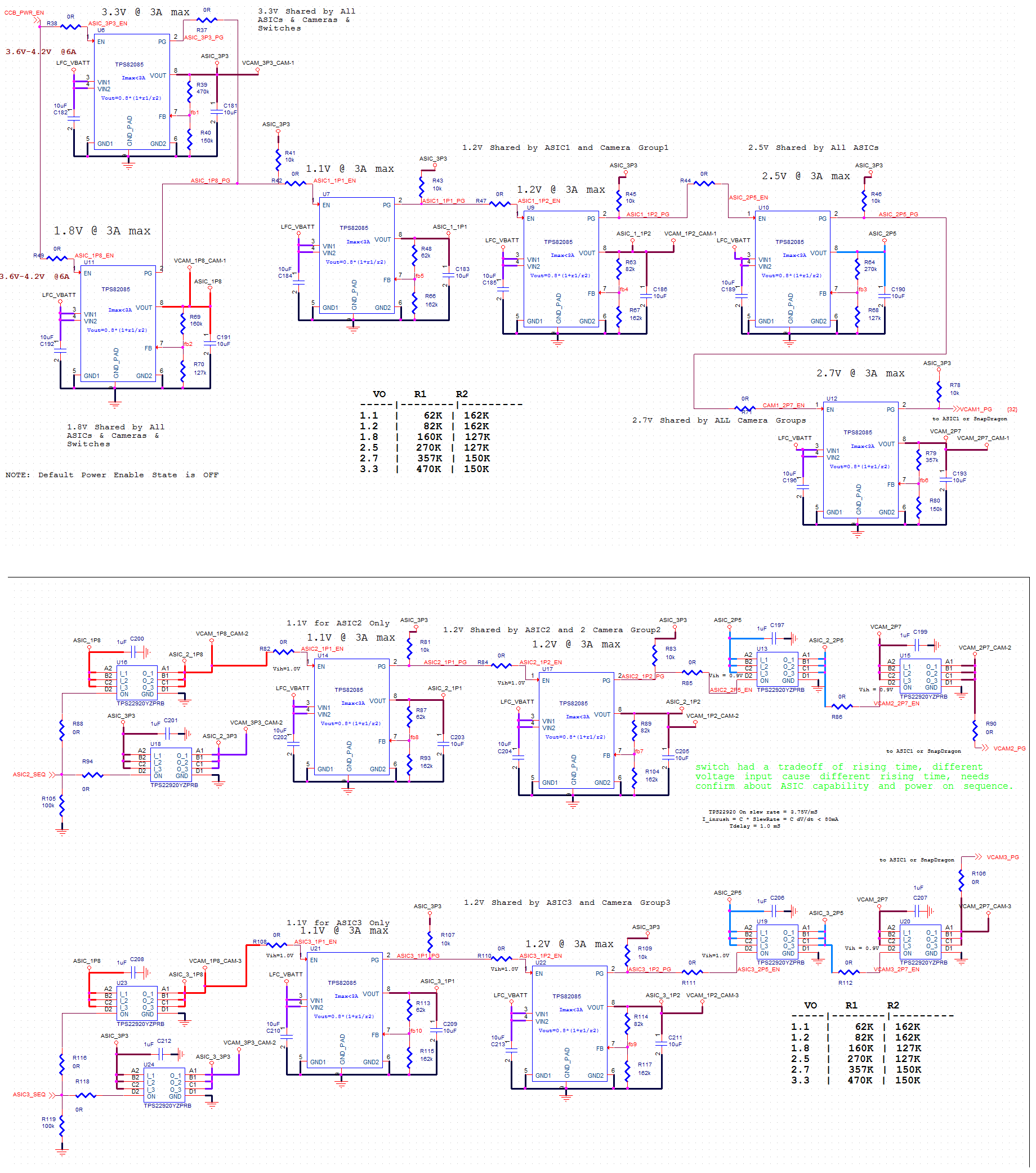
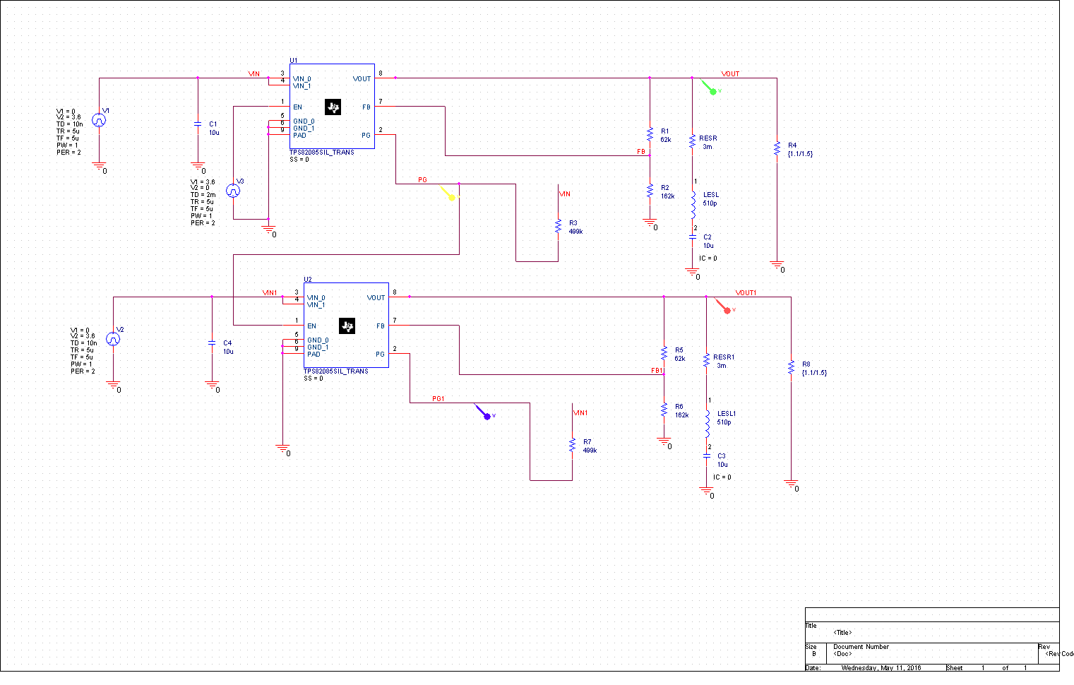
I have 10 numbers of TPS82085 in my design. I want to include all these 10 reg in my simulation to do the transient , Power up seq.

Now the issue is,

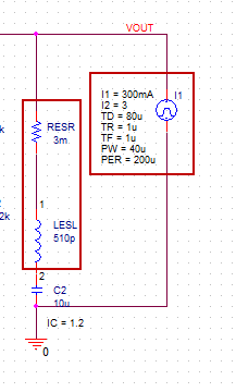
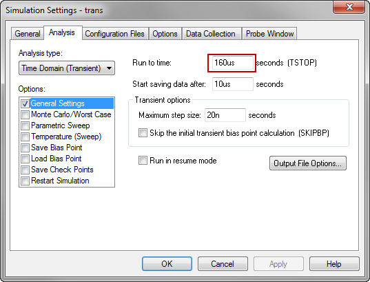
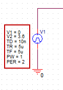
I am using the Pspice deck downloaded from the site & if i am running 10ms transient simulation for one regulator, it stops.

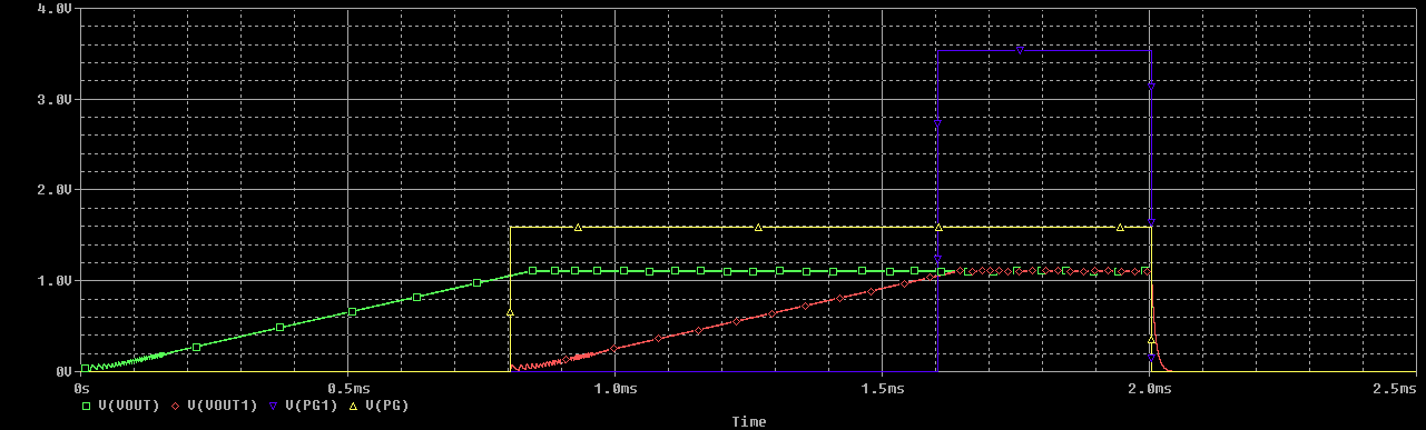
Attached please find the schematic & the pop up message while running simulation where it stops to run. Reporting convergence issue ??
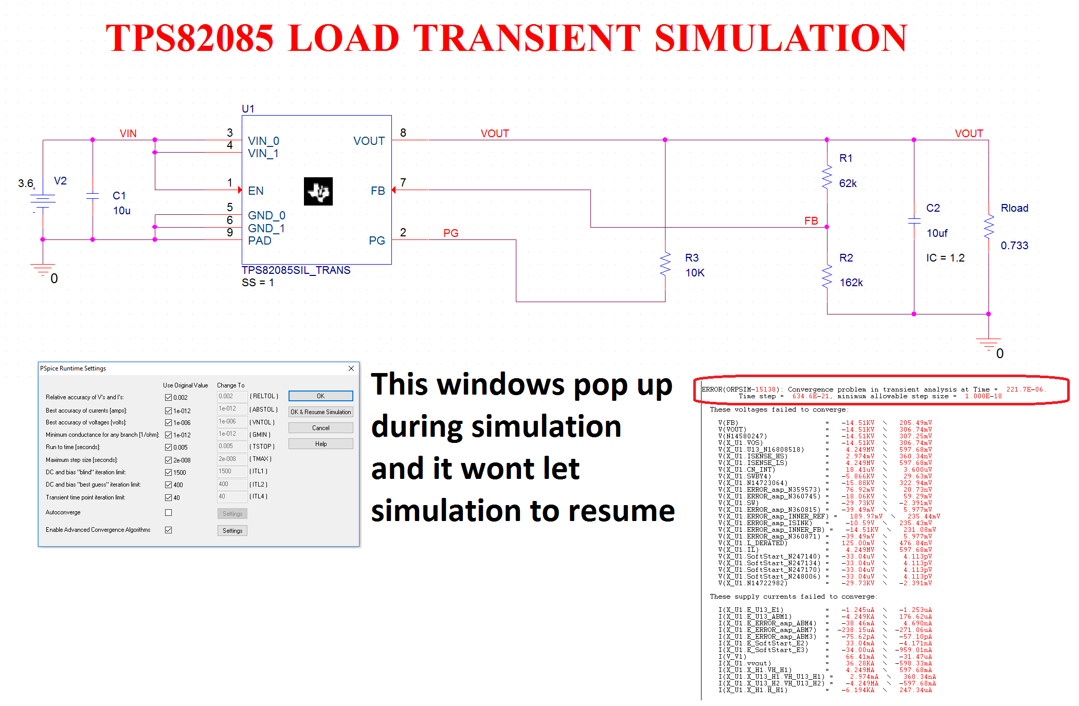
Thanks & Regards

Jones

  • Jones,

    I need a little more information about your simulation for the project.

    First, why would you use the load transient simulation (which assumes a steady state model and steady state conditions before applying the transient) to do a startup sequencing simulation? I would suggest using the startup simulation.

    Second, are you familiar with convergence issues with simulations? If not, you may wish to do some research on convergence. If you are familiar with convergence issues, you would know that there are settings in the PSpice .sim profile that are used to allow the simulation to run (the values of the variables in the window that pops up - PSpice Runtime Settings). You can modify these and continue the simulation in some cases, however, you will need to get the correct variables and values to allow the simulation to continue. This can be very difficult.

    Finally, are you planning to run 10 converters at the same time? If so, please prepare for your simulation time to be very long (several hours). A single device running for 10ms in simulation time will take about 3-4 hours.

  • Hi Britt Brooks,

    I understand like you are asking me to use startup simulation deck for load transient analysis ?

    I don't know abt convergence issues.

    Run time is not an issue and that's why I chose licensed pspice rather than free tool Tina.

    Shall I ask for a simple transient analysis deck from TI where I can just change my circuit values and run simulations?

    If I need more time to tweak the deck, I would prefer to change my regulator

  • Jones,

    What are you trying to simulate? Are you trying to simulate a Load Transient (a simulation where the system has started up and the load changes) or are you trying to simulate sequencing of the 10 converters (a simulation where each converter is initialized and started based on the order provided for each converter)?

    The .zip file provided from the product folder has two test benches in it, a Load Transient test bench and a Startup test bench. In your original post, the picture you provided had the title from the Load Transient test bench, but the schematic did not show a load transient at all. You mentioned sequencing which requires the startup simulation test bench, not the load transient test bench. Based on this information, I asked the questions to help determine the best way to help you get the information you require.

    Convergence basically determines when a simulator can go to the next solution point. There are many settings inside the simulator that control when the solution has been reached, within the prescribed tolerances. A convergence error occurs when the simulator cannot determine a solution inside the prescribed tolerances that are set by the simulation parameters. These parameters may need to be tightened or loosened to help the simulator find the proper solution. The methodology for solving convergence issues is determined by the circuit, simulator, and simulation parameter values. If you are planning to run simulations, you will need to become familiar with the convergence parameters for that simulator.

  • Thanks Britt.

    1. I want to simulate the Load transient (Load changes after 3ms) for one regulator & also the Power seq /Power down seq with 10 numbers of TPS82085.

    2. When i am using the TI - load transient deck (set for 900us run) & i am changing to 5ms run, the simulation time is take more than 3 hours.

        Also i am facing the same convergence issue. All i have changed only the feedback resistors for 1.1v

    Can TI support on review our power circuit schematics. I am using 10 numbers of TPS82085 & 2 numbers of TPS55340.

    Ours is consumer product & going for mass production. 

  • Jones,

    Here is what I would do:

    1.) For the load transient, I would use the Load Transient test bench and configure the current source for your dynamic load. You will specify the starting current (I1), the current during the transient (I2), the rise/fall time (TR and TF) of the transient, and the duration (PW) of the transient. The TD value is the delay before applying the transient (I would make this 80u). Since the simulator does not care how long the device has been in steady state, you do not need to wait 3ms to apply your transient. The steady state is reached for 1.1V at about 80u with your 10u capacitor. I would investigate the parasitics of the output cap (ESR and ESL) since these will effect your response. You have removed them in the provided schematic, however, they are present in the Load transient simulation from the product folder.

    Make sure that you set your simulation to run for the TD plus the PW plus the TR and TF values (with a little padding for the settling from the fall time) in the simulation profile (PSpice-->Edit Simulation Profile)

    For the sequencing, do you plan on turning off/on the converters with the EN pin? If so, I would use a separate Voltage source tied to the EN pins (Vpulse source) of each converter and configure it for your sequencing for the converter when you want to turn it on and off. Unfortunately, you will need to use the start up simulation for this test as each converter will have to start up individually. You can tie the inputs to the same source if you wish or make them separate, your choice.

    Your simulation will take a very long time to run if you want to see 10 converters sequence on and off. I would only run the simulation long enough for all 10 to cycle through. Startup takes about 1ms per converter, so you will be running the simulation for at least 10ms. I have tested the startup simulation and it will run without any issues for more than 10ms, however, it may take several hours to run. Your sequence will determine exactly how long you need to run the simulation.

    2.) I would not run the load transient simulation for that long. Since it is using the steady state model, you do not need to run the simulation that long. You did change the FB resistors for 1.1V, but you also removed the dynamic load (current source) and added a fixed 1.5A load. That is not a load transient simulation.

  • Thanks for the detailed explanation . I will try your recommendations.

    Please provide feedback for the below question

    Can TI support on review our power circuit schematics. I am using 10 numbers of TPS82085 & 2 numbers of TPS55340.

    Ours is consumer product & going for mass production.
  •  Hi Britt,

    Please find my schematic where i have connected all 10 regulators .

    I am enabling one regulator with the PG open drain output with the pull up.

    Kindly let me know ,how i can use the start up deck to verify the sequencing works perfectly.

  • Jones,

    Here is the example schematic I used:

    Here are the results. I used the EN pin on the first device to disable the first device. When PG goes down, the second device is disabled as well. You can do this for all of your converters, however, I think a simple case should give you enough information to see that the method should work.

    The simulation runs for 2.5ms and takes a couple of hours to run.

  • Thanks a lot Britt...

    If possible please share me the deck.

  • Hi Britt,

    One last query, can you let me know why the PG of Regulator 1 in the above simulation doesn't reach to 3.6v.

    Please clarify

    Thanks & Regards

    jones

  • Jones,

    The resistor I was using from the original design was 499K. The resistor internal to the device on the EN pin is 400K, so you were seeing the voltage divider. I thought I had changed it to 10K previously which gives you a much closer value to 3.6V (about 3.5V). I do not believe that this is a "real" effect, I believe it is because of the way we have modeled the EN pin in the model. You will see some amount of loading from using the PG pin as your EN signal, but it should NOT be that drastic.