A related question is a question created from another question. When the related question is created, it will be automatically linked to the original question.
If you have a related question, please click the "Ask a related question" button in the top right corner. The newly created question will be automatically linked to this question.
TINA/Spice: How to Design multiple output winding transformer
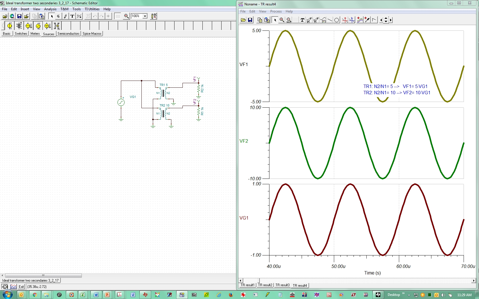
If you call "ideal transformer", you can just put the primaries in parallel, as shown below:
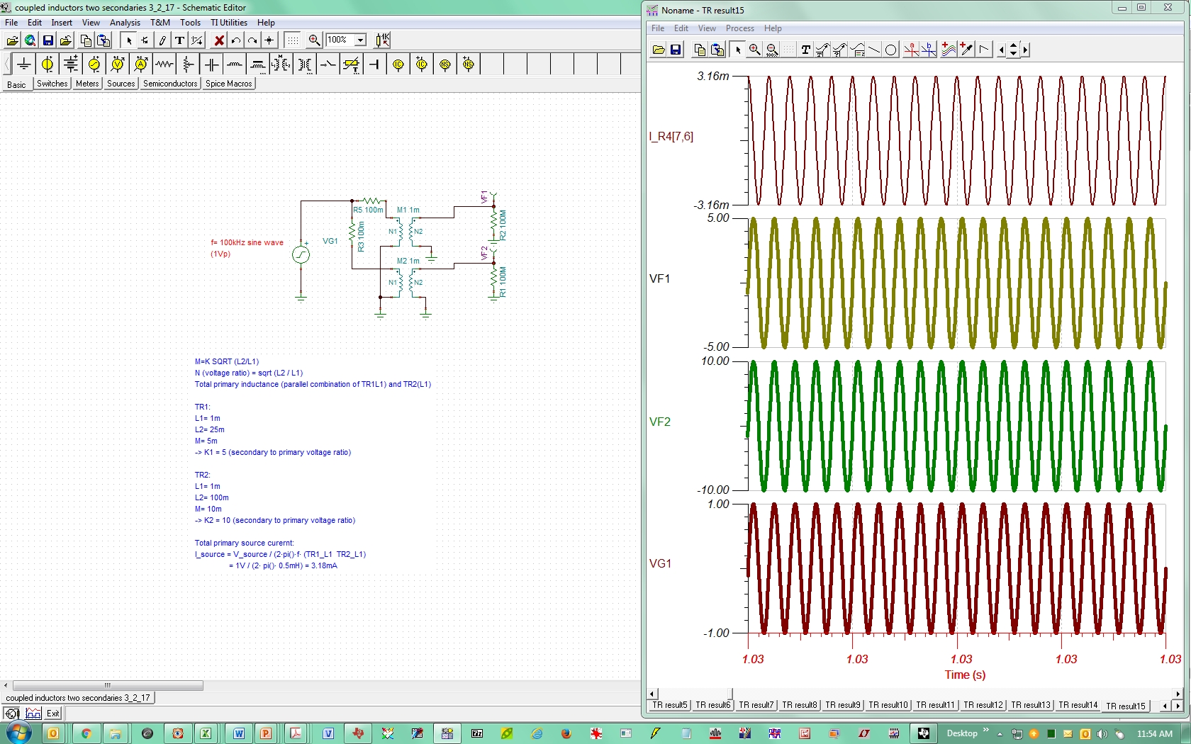
You an also do it with Coupled Inductors, as shown below. The source "sees" the parallel of the two secondaries inductance (ignoring any current related to the secondary load). So, I believe in effect the the combination of the two coupled inductors connected this way, behaves the same as three coupled inductors.
Here are the two respective TINA-TI files for reference:
I forgot to mention that for the coupled inductor case:
a) Primary input impedance: The top trace is the current through a small resistor placed in series with the source to read the current (+/-3.16mA) to verify the loading on the source. I later removed this resistor (R4) which is not in the TINA-TI files I shared.
b) Simulation Start: I had to run the simulation Start for a long time to make sure the transients have settled (that's why the long simulation time) because I wanted to ensure the DC "average" source current is 0 (as it should be when only driving two transformers).
c) Simulation Artifact / Convergence: The other very small resistors (R3, R5) in series with the coupled inductor windings were needed for TINA-TI to converge. They don't serve any purpose for the circuit (just for simulation).
I think it's easier to follow the method that my colleague Britt Brooks has recommended here as "subcircuit import" to build a transformer with arbitrary number of secondaries: