Other Parts Discussed in Thread: OPA857
Hi,
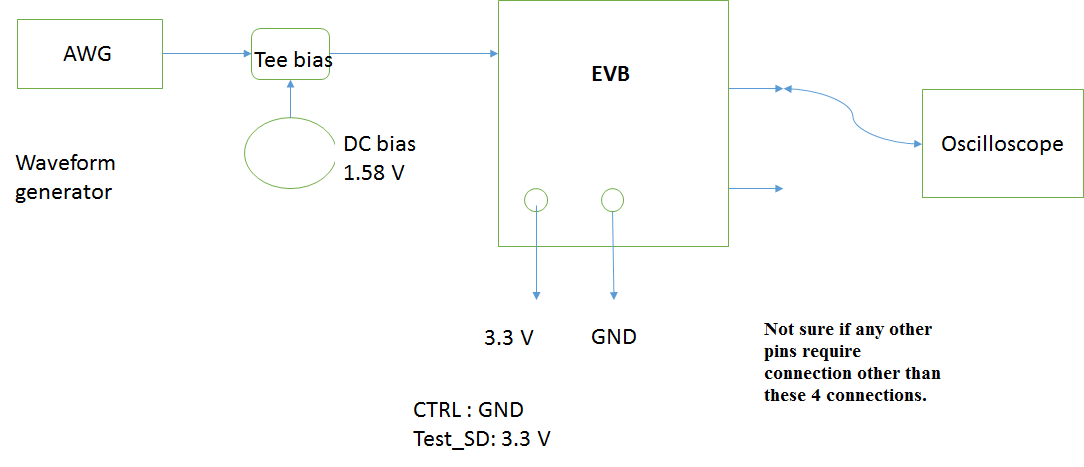
I am evaluating TIDA 00978 module. Right now, I am setting up the test mode for this EVB. A sine wave(100 KHz, 500mV peak-to-peak) generated from Tektronix AWG is sent through a Tee-bias and then sent to the input of the amplifier. As per the test mode requirements, I have set the CTRL and Test_SD voltages. To power up the EVB 3.3 V and GND terminals are also connected.
I was unable to find any signal in the oscilloscope. For CTRL=>Ground, I am expecting a gain of 5K approximately. Since, I could not find desired signal on scope(from both the outputs), I am uncertain about few connections. The EVB documentation mentions about different modes of testing. However, the Schematic shows some pins connected to Vcc and GND. I am not sure, if they have to be connected alongside the CTRL and Test_SD.
For example, On J6, there are Vcc and GND pins. Do they require to be connected along with CTRL while trsting in the Test_mode. The diagram referring to test_mode does not contain information about these pins.
Similarly, Vcc and GND of J5 and Vcc of J4. Do they have to be connected to their respective designations or is it just the pins shown in the diagrams(documentation: Reference design for extending OPA857 transimpedance bandwidth)
The EVB does not contain any indicator that shows its status, whether it is On or OFF. I am handling it carefully with ESD protection. How do I check if there are any fault/damage?