


Other Parts Discussed in Thread: TPS2549, LM73605
I'm reviewing the reference design and am not sure of the circuit for the FB/CS
The standard FB resistor divider appears to be R5(47.0k) over R9(10.0k) however there's also R10(200k) in parallel with R5
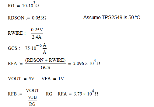
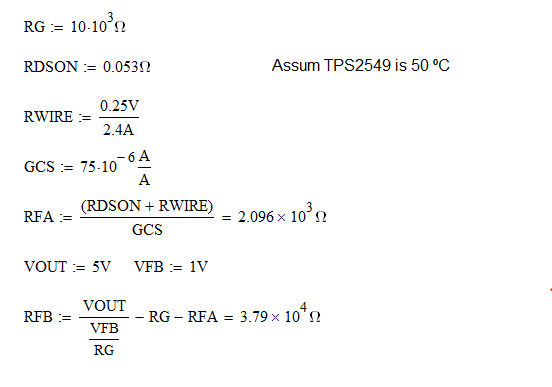
Looking at the cable compensation design procedure in the TPS2549 datasheet (p18, p29, p31) you should be adding R11(2.1k) and C14(22nF)
- Reading the LM73605 datasheet it is recommended that Rfbbt is 10k to 100k although you can use larger values.
- Rfbb = [Vfb / (Vout - Vfb)] * Rfbt where Vfb = 1.006V for the LM73605
- From the schematic we know that Rfbb =10k and Vout =5V so that means Rfbt should = 39.7k
- 47k in parallel with 200k is 38.1k
- standard 1% resistors in this range are 38.3k, 39.2k, 40.2k
Seems to me that R10 shouldn't be there and R5 should just be a 39.2k
Now there's also the value of R11(2.1k) which is call Rfa in the TPS2549 datasheet and is calculated with Rfa = (rds + Rwire)/Gcs. In Table 4 (p31) they list Rtotal=0.42 (which is rds + Rwire) and Gcs as 0.075mA/A. Using those values yields a Rfa = 5.6k. Back calculating from the value in the schematic yields a Rtotal of 0.8820 which is basically double what the TPS2549 datasheet uses.
Of course cable resistance will be all over the map but it would be nice to have some consistency or explanation on what might be better design practices. You're not going to be able to control what cable the customer uses so maybe there's no best answer?
The parallel resistor still has me scratching my head though.

