This thread has been locked.

If you have a related question, please click the "Ask a related question" button in the top right corner. The newly created question will be automatically linked to this question.

TIDA-010015: Power supply design getting Turned OFF

Part Number: TIDA-010015
Other Parts Discussed in Thread: UCC256301

Hi All,

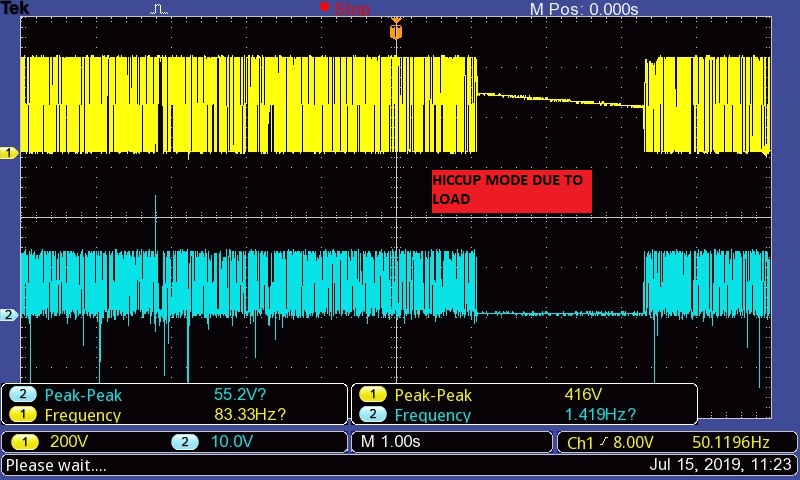
This TIDA-010015 model redesigned for our design and this was designed for 600W so some up gradation done with the design. During bringup we could see this power supply automatically shut down after loading 3A but it should be capable of giving 25A. 

Please advise what could go wrong and where i need to work/look to over come this issue. 

Expecting expert advise. 

  • Hi Balasubramani,

    Thanks for your interests in TIDA-010015.

     Do you mean your board could work normally with 25A load, but it will shut down with 3A load. Right?

    Here is my suggestion as below:

    1. Confirm PFC will shut down or LLC will shut at 3A load;

    2. Decrease the output load from heavy load to light load, observe the load level of shut-down;

    3. During the step 2, monitor the output voltage and resonant current waveform. Check if there is abnormal phenomenon before shut down.

    BR

    Cheng

  • Hi Cheng,

    After this shutdown, the output not able to see and the is PFC  output voltage keep on trying to stable , but the LLC not switching properly and this lead no switching at the secondary side.

    Checked impedance at all components it is fine , but we could not find the reason behind the LLC section failing to operate.

    We are new to this domain we may need expert's help to over come this issue. 

    Let us know how to debug this issue and please let me know how to probe this resonsant current waveform , we dont have differential cable instead we have high voltage single end cable. 

    please help here. 

    BR

    Bala

  • Hi Bala,

    Please share with me the exact schematics an pcb file you use now.

    I need to review them, and then provide my suggestion.

    BR

    Cheng

  • Hi Cheng,

    Can you share me your mail ID please. since this design file have our customer details and we dont want to express in forum . 

    Expecting your co-operation and support on this issue. 

  • Hi Bala,

    Please send me the schematics and pcb file to his Email: cheng-liu@ti.com

    Thanks!

    BR

    Cheng

  • Hi Cheng,

    I have shared the design files please check and revert.

    BR

    Bala

  • Hi Bala,

    Here is my question and suggestion, please check it on your board.

    Could you check the protection type? Hiccup or Latch off?

    Measure the LO waveform, check the hiccup time is about 1S or not?

    Remove R49 to disable OVP function, and then check if the board will shut down or not?

    Remove R66 to disable burst mode, and then check if the board will shut down or not?

    UCC256301 includes three-level over current protection, output over voltage protection, input voltage OVP and UVP, gate driver UVLO protection, and over temperature protection.

    You can check the protection type one by one.

    BR

    Cheng

  • Hi Cheng,

    Thanks for the suggestion . Now we are planning to validate this PFC section alone by removing LLC section and we are going to use external bias supply. Could you tell me whether is this safe to work this PFC without Load at the high voltage ?

    Please let me the possibilities. We want to make sure PFC is working before jumping to other section. 

    BR

    Bala

  • Hi Bala,

    PFC is OK without load. 

    However, I want to mention you that please take care of the high voltage with long hold up time due to no load to discharge.

    Also when you use external power supply for PFC controller, please make sure the LLC controller is disconnected completely with PFC stage.

    If not, the high voltage startup circuit of UCC256301 will be coupled into the external power supply, and it is dangerous.

    BR

    Cheng

  • Hi Cheng,

    Thanks for the fast response. Will test the PFC accordingly and keep you posted. 

  • Hi Cheng,

    As we working on the next board facing same issue like without load this board good to provide expected output, but when we are loading the power supply about 20W (almost 1A) this power supply goes HICCUP mode and it keep on ON/OFF at the secondary side.


    Please find the images captured.

    Yellow Waveform- HO

    Blue Waveform- LO 


    Issue 2:

    After continuous running LLC HB's FET got damaged and PFC IC also got damages. This is happening at the 3rd board. 

    Please let me where we need to look for to solve the issue. 

  • Hi Bala,

    If you have any progress, please let me know.

    Thanks!

    BR

    Cheng

  • Hi Cheng,

    We found the root cause and board working fine as per our requirement with AC input ,but we are facing issue with DC input voltage. 

    Note: AC input 220VAC, DC input 120VDC

    We are yet to find the root cause for the instability with the DC power supply . As per the observation with DC input are Bulk cap , Inrush limit mosfet getting hot and we this Regulated 15v aux voltage rail got shorted after loading 7.5A load.

    Please share your thoughts. 

  • Hi Bala,

    Do you mean there will be two types of input voltage, AC input and DC input, right?

    There will be issue only at DC input, right?

    BR

    Cheng

  • Hi Cheng, 

    Yes. You are right. 

    We have used 120VDC as input as of now, yet to check with increase in input voltage. 

    Let me have your thoughts.  

  • Hi Bala,

    When the input voltage is 120VDC, the PFC stage will be active or not?

    I mean PFC will generate 400VDC bus voltage or not at 120VDC input?

    If PFC is inactive, the 120VDC input voltage will be too low for LLC input due to the gain ability of LLC.

    If PFC is active, you can check PFC stage can work well or not at this input voltage and generate 400VDC bus voltage.

    If PFC stage could work well and generate 400VDC bus voltage. Next you can use external DC source 400V to check LLC stage could work well or not.

    Waiting for your evaluation results.

    Thanks!

    BR

    Cheng

  • Hi Bala,

    Have you checked the root cause is from the the gain ability of LLC or not?

    Waiting for your evaluation results.

    Thanks very much!

    BR

    Cheng

  • Hi Cheng,

    Please find the response below.

    When the input voltage is 120VDC, the PFC stage will be active or not?

    --Yes it is working and it has generated 390VDC

    I mean PFC will generate 400VDC bus voltage or not at 120VDC input?

    --Yes

    If PFC is inactive, the 120VDC input voltage will be too low for LLC input due to the gain ability of LLC.

    -we are good here

    If PFC is active, you can check PFC stage can work well or not at this input voltage and generate 400VDC bus voltage.

    -- We are good here. 

    If PFC stage could work well and generate 400VDC bus voltage. Next you can use external DC source 400V to check LLC stage could work well or not.

    --Not tested yet , since output generated we have not tested this case.

    So far we have tested with 135VDC since the brownout setting almost close to 120V could have caused this issue earlier. Yet we need to adjust the brownout settings and test with low DC voltage . 

    We facing new issue with the board like after testing over current test some board not working properly like out of 5 times 4 time board not powered properly. 

    And with Low AC input some time causing problem like startup not properly working that leading board instability with low input voltage . 

    please advise here

  • Hi Bala,

    This is my suggestion as below:

    1. For the issue at 120VDC input, the LLC will shut down when output load is lower than 3A.

    Form your description above, I suggest to use external 400Vdc as the input voltage for LLC, and then check LLC could work well or not at full load range.

    This method could help you know if there is any design issue for LLC stage or not.

    Also, what is the test result for 135VDC input voltage?

    2. For the new issue the board couldn't work properly after testing over current tests.

    What is the BLK setting? The input voltage for LLC start up? If the input voltage is too low, it may cause the PFC stage to be protected.

    Also, I will forward this question to the IC designer to check it.

    Thanks!

    BR

    Cheng

  • Hi Cheng,

    Will try to test the LLC with external supply (But we dont have source that provide 400DC in our lab)

    With 135VDC we have tested with our full load for 24hr atleast. we are good with 135VDC here.

    BLK startup voltage set as per the reference design . we have not changed anything.

  • Hi Bala,

    OK.

    If the board couldn't work well at 120VDC, I suggest you should use external source to test the LLC stage independently.

    I suggest you could capture the 400V BUS voltage and driver signal of LLC, and check the startup input voltage of LLC.

    Make sure the LLC startup at a relatively high input voltage.

    BR

    Cheng 

  • Hi Cheng,

    One last query before doing further test cases, While testing with low voltage we are facing many issue whether it is AC or DC the problem arriving different location and many time board not powered at all unless we are changing the IC and one more issue in with Low input voltage is problem at Fusible resistor (R12) at the schematic, and we observe Smoke in that section . 

    Let me know where to debug and what need to be monitor to avoid issue in the future.  

  • Hi Bala,

    Based on my debug experience, it is better to separate the issues and then resolve it independently.

    When you analyze an issue, please make the circuit to be simplest. 

    If the analyzed circuit is complex, it is hard to find out the real reason.

    For the R12 smoke issue, I guess it is from the power rating is not big enough.

    During startup time, there will be big current flowing through R12.

    If the bearable power rating is not big enough, it will burn.

    It is suggested to use higher power rating resistor to replace it.

    I suggest you use an 0ohm jumper wire to short R12, and resolve the other issue firstly.

    Thanks very much!

    BR

    Cheng