This thread has been locked.

If you have a related question, please click the "Ask a related question" button in the top right corner. The newly created question will be automatically linked to this question.

TIDA-00367: SMPS testing

Part Number: TIDA-00367

Hi,

Following the thread

Have successfully built the SMPS and it appears to work in NO LOAD situations and with a 55W load too (24V/55W lamp load). The output voltage is about 19.6V. The SMPS appears okay with Short Circuit protection too.

Things went well, thanks to the folks who have chimed in on various aspects.

The issues that I've been seeing:

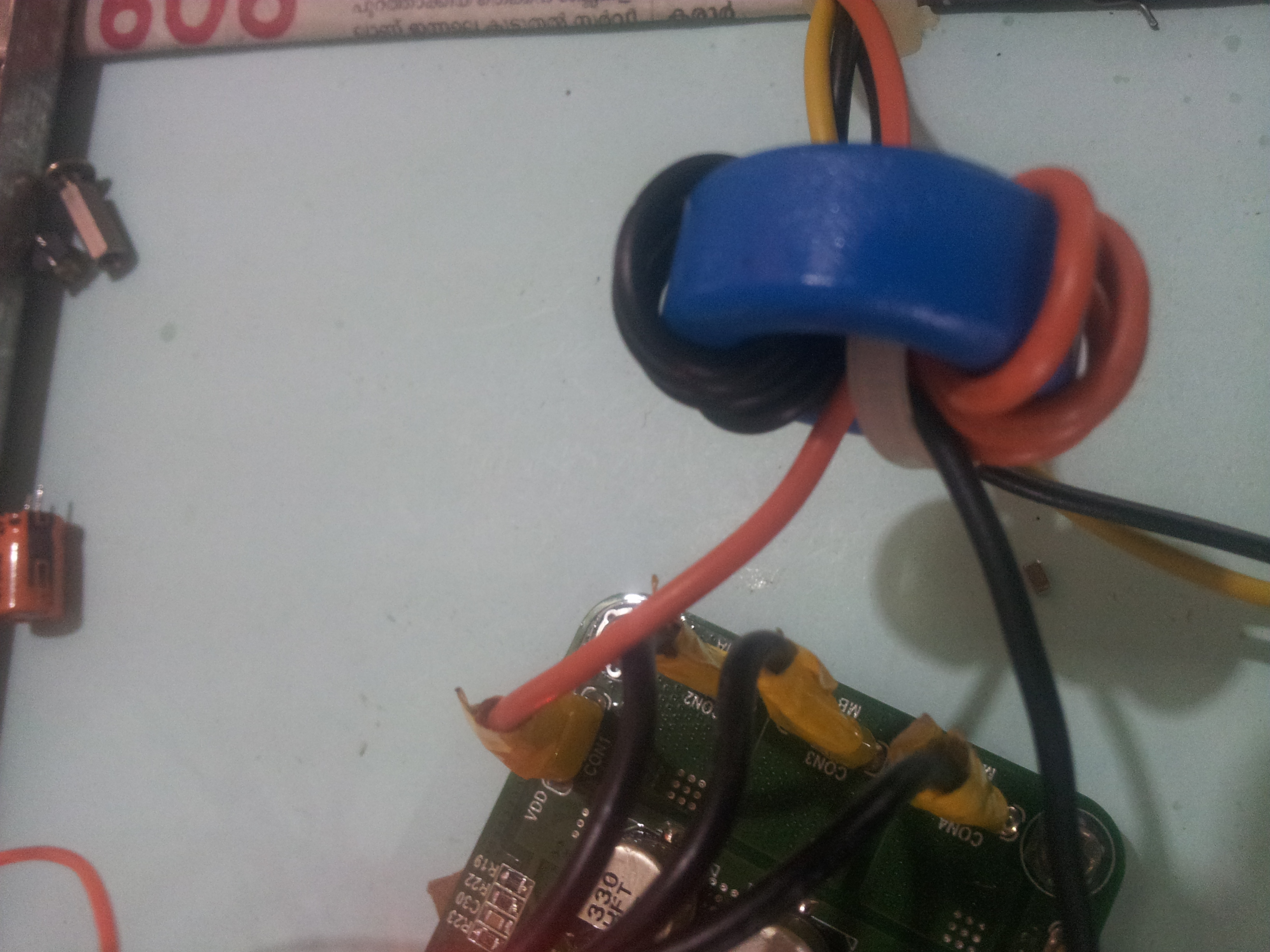
#1. There's a small noise. The noise varies with the load at the output. Initially, I thought it is from the transformer, that doesn't seem to be the case. The transformer has been manufactured by a professional vendor. It has been varnished, baked and so on.

Where else can the noise come from ? Looking around, I see people talking about capacitors making the noise, Is it really true ?

#2. Changed the load from the lamp to a Brushless DC motor and it's controller. The setup works with a commercial off the shelf SMPS quite okay. But when I do power from the SMPS under consideration, the setup goes really crazy. It appears that the controller gets RESET due to noise from the power supply.

The funnier part, is that the same motor and controller ran well from the SMPS under consideration for about a week. It was all of a sudden, I had a failure of a MLCC, Gate driver (DRV8305) and a MOSFET pair with the BLDC controller. After that the issue was identified and the motor runs perfectly with everything else, except with this SMPS that we are talking about.

As a result for testing purposes, added a 10,000uF/50V electrolytic capacitor along with a 470uH toroid inductor as a LC filter to filter out the power supply ripple. Still, with the LC filter, the motor and it's controller behaves exactly the same.

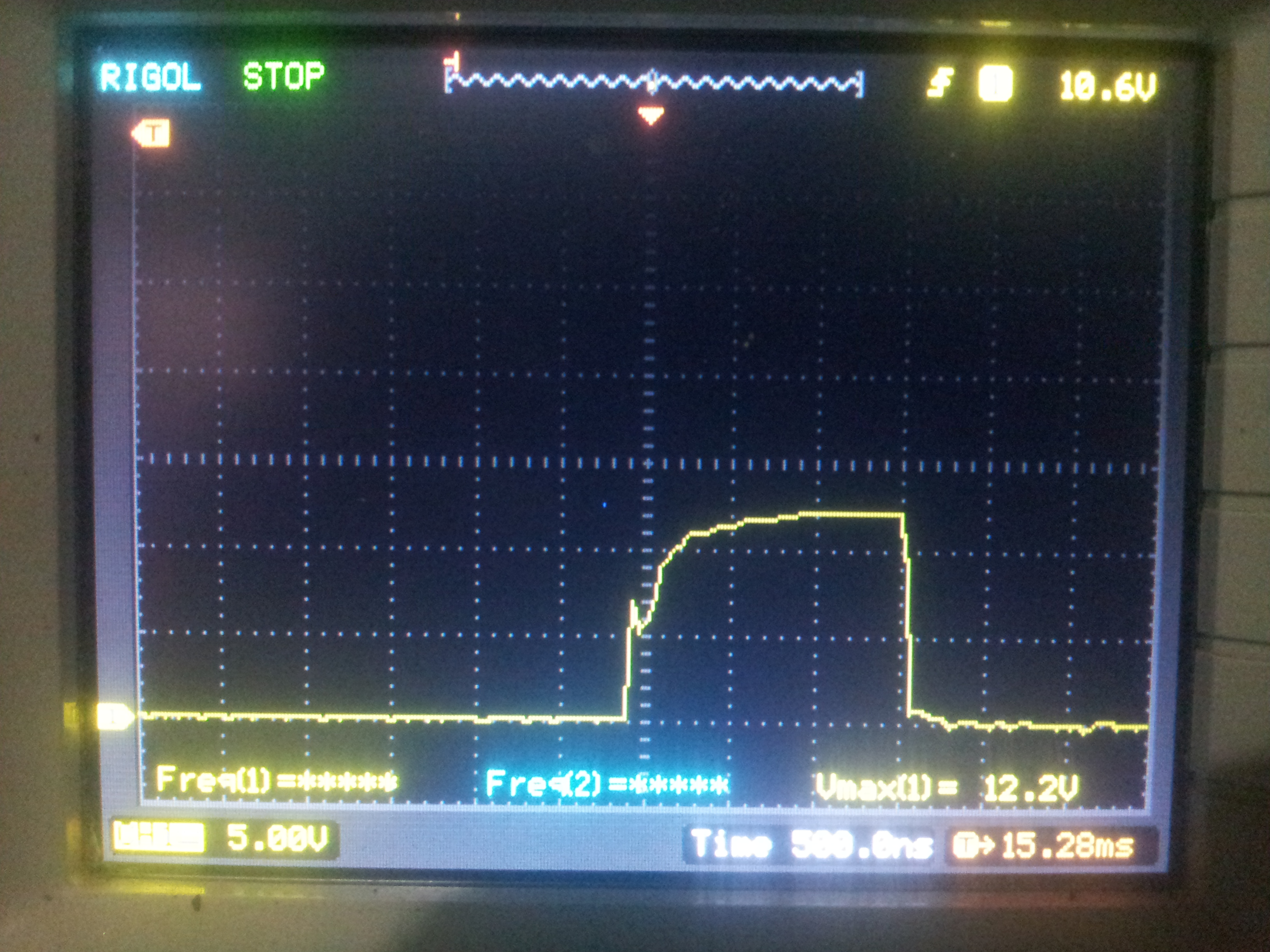
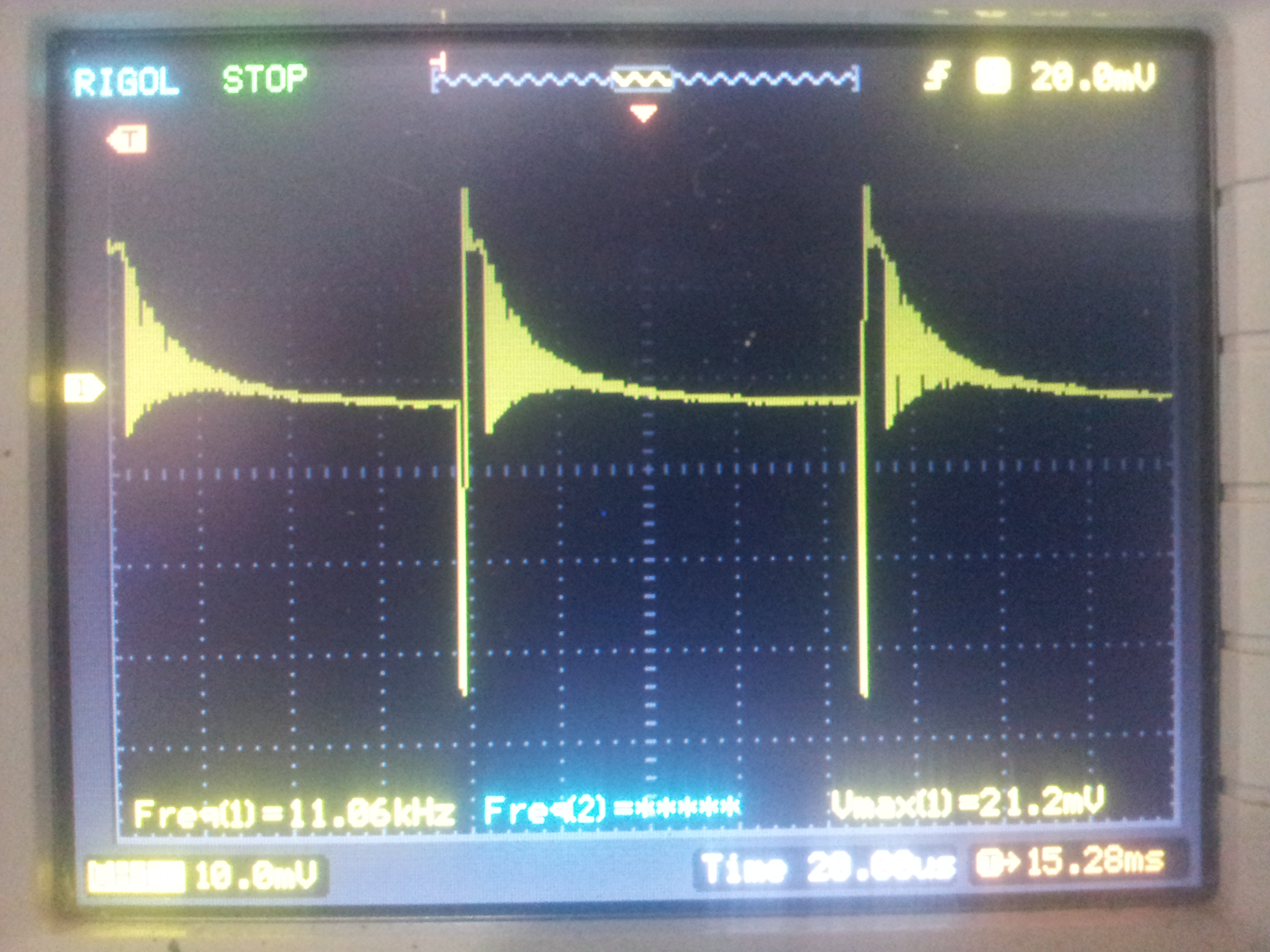
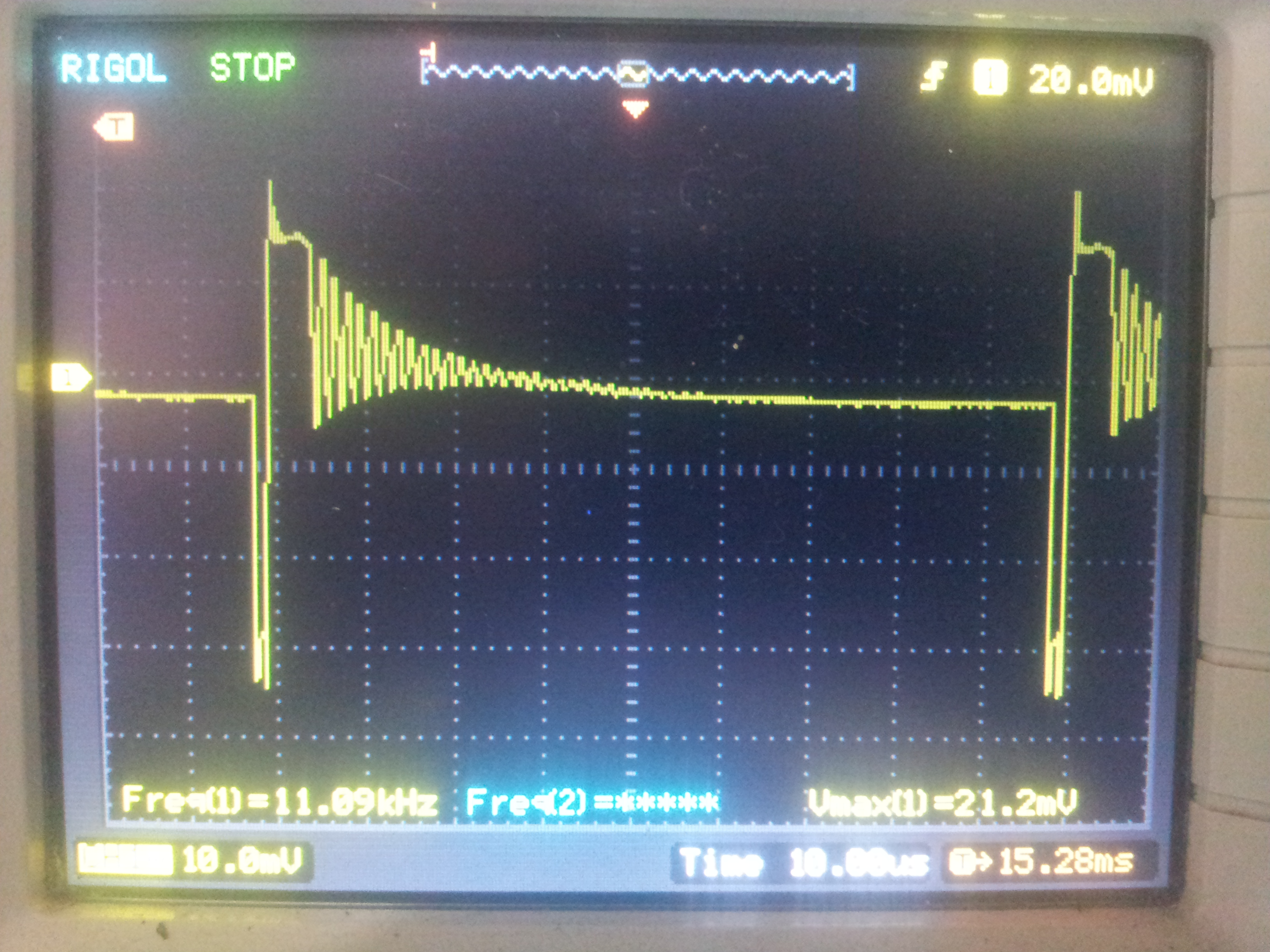
Tried looking at the ripple at the SMPS output with the load, the ripple voltage is less than 0.5V, looking at the waveform on a scope connected to the power rails.

Now, my query is, how to identify the issue with the SMPS ?

Thanks,

Manu

  • Update:

    The following tests conducted with a 12V automotive halogen lamp load

    @60W V=0V (SMPS shuts down, the sound of a cricket chirping at an interval of about 2.5s )

    @55W V=19.82V (The same sound as in the case of a NO LOAD, but it is at a slightly reduced level)

    @21W V=20.05V (the same sound as in the case of NO Load)

    @ 5W V = 20.14V (the previous sound exists, in addition a kind of braking noise which is slightly more prominent)

    NO LOAD V= 21.7V (the sound of a square wave, similar to a mosquito buzzing)

  • Update:

    Tried capturing the MOSFET gate waveform with an oscilloscope: Please find attached images.

    Funny to say, the weirdness as the scope probe was connected between the MOSFET Gate and Ground, the weirdness vanished. (That said, there is still a RESET happening but that's in the order of a few minutes.)

    Could this probably be a decoupling issue ?

    Thanks,

    Manu

  • Update:

    Following the tip with situation improving when the scope probe was introduced at the FET Gate, tried looking at the electrolytic capacitors, which looked okay, but nevertheless the electrolytic caps and the decoupling capacitors were replaced.

    There was no visible change at all, with those changes.

    The thought switched to common mode noise:

    Looking at the 1000pF capacitor connected in between the primary GND and the Output GND, the capacitor seemed to be fine, measuring the capacitance.

    Adding another 1000pF in parallel to it, reduced the issue very much, but the issue still does not go away completely.

    What else can I look at, which contributes to common mode noise, if that's the culprit ? Is there a possibility of transformer degradation, worsening the Common mode noise situation ? Any thoughts, someone ?

    No one's reading this thread ? Any suggestions ?

    Thanks,

    Manu

  • Feeling a bit silly replying to my own post, but hoping that someone would reply:

    #1. Measured between C2 GND and T1 GND Pin 11. The spikes are recurring, I guess these spikes are the one RESET ing the C2000 controller eventually. The voltage is between 2 GND ends!. It does look a bit strange, doesn't it ?

    #2.  The voltage waveform at the output of T1 Pin 8

    #3. The MOSFET Drain - PRI GND waveform

    #4. The FET Drain waveform with the LOAD connected and BLDC motor running.

    #5. The same as #1, but after removing C1(1000pf) across the main rectifier D2, with the LOAd connected and running. The noise amplitude seems to have reduced in comparison to #1, but there appears to be more noise ?

    Can someone please have a look ?

    Thanks,

    Manu

  • Update:

    The problem mostly fixed by adding a Common Mode Choke at the SMPS output. Attached picture. So, the culprit was indeed Common Mode noise as identified in the previous post. That said, even though the problem has nearly been fixed, once in a while, some noise does really pass through.

    Any suggestions to to filter it out ?

    Maybe increase the number of turns, or maybe even use copper wires instead ? Any suggestions ?

    Thanks,

    Manu

  • Some more update:

    I was able to get rid of the noise as well as the audible noise when I introduced a Load of ~0.55A.

    Dummy Load schematic

    With this load in parallel to the BLDC controller, all the odd behaviour with the BLDC setup vanishes away for good.

    Looking at the UCC28630 datasheet, it appears that the audible noise as well the weird behaviour occurs most likely

    when the UCC28630 is running between the P0-P1 region. Also, when the SMPS is operating in that region, there is a sound of a mustard seeds bursting open in hot oil. It is with that noise, the BLDC controller goes berserk and reset's itself.

    The various modes appear to be controlled by Vcs, which is the the same as CS Pin Voltage ?

    Can someone clarify, please ?

    To increase Vcs can I simply increase the CS resistor value and expect that the UCC28630 moves operation away from P0-P1 region to P1-P2 and avoid the dummy Load altogether ?

    Any thoughts ? Anyone reading this thread ?

    Thanks,

    Manu

  • Hi Manu,

    I will contact designer to help answer this question, thanks.

    BR

    Jason

  • Hi Jason,

    Much appreciated, awaiting feedback on the subject.

    Thanks,

    Manu

  • Hi Manu,

    I have forward your questions to Designer S, Ramkumar (ramkumar.s@ti.com), or you can contact him by email directly, many thanks.

    BR

    Jason

  • Hi Manu,

    Do you have a single output  or multi output?

    Incraseing the Current sense resistor will help reduce this situation but not completely. It is better to put a 100 to 200mW dummy load at the output just to keep the system from moving into OVP.

    Reading through your earlier post, I assume your motor driver board might have been misbehaving because of high ripple at the output when the system going into OVP.

    Best Regards,

    Ram

  • Hi Ram,

    Thanks for the response.

    I have the exact same transformer design, what you provided previously (in the other thread, link with the first post of mine. Sorry, about the multiple posts. Have been tinkering to find the problem and hence), without any changes at all. 5 and 4 turns on the secondary respectively. Have a TLV1117 connected to the 12V (4T) tap. A LED is alone connected to the TLV1117.

    Tried putting a 0.33 ohms Current Sense resistor instead of the 0.12 ohms, but that did cause SMPS shutdown. The SMPS will run, I guess for about 1 second or less and then would shutdown. I guess that was OVP kicking in ?

    A dummy load 200mW appears not to be sufficient at all. Tried different loads, with the 0.12ohms CS resistor. The driver needs a load of about 0.5A (empirically, the motor driver board works okay with 0.54A lamp load and not either at 0.35A a different lamp load) (at 21 - 20.6V of course).

    Another thing to notice is that, adding a common mode choke with 2 capacitors also helped in reducing the issues, but that did not help completely though.

    Wondering whether a design change in the transformer, in adding a shield and or a shield winding would help as in the UCC28630 EVM board ? To reduce the common mode noise ?

    But in the given context, given that the primary sandwiches the secondary, shield would be necessary between both sides of the secondary winding ?

    Just thoughts, would like to know what your thought on the following:

    The Yellow color is the insulation tape. Brown color is Copper wire / foil. Orange color is copper wire that's used as a shield winding along with the Bias winding, as in the EVM design.

    Having 2 shields reduce the efficiency ? A small mistake in the drawing that the top shield should have been between the next lower layer ?

    Or is that superfluous altogether ?

    Thanks,

    Manu

  • Hi Jason,

    Much appreciated.

    Continuing the discussion with him. Issue still not solved, looking for a proper solution on the issue.

    Thanks,

    Manu

  • Hi Manu,

    Let's contact designer again, sorry for waiting.

    BR

    Jason

  • Hi Jason,

    Wondered whether he is active on the forum, hence tried sending him an email with the address that you gave me earlier. Will wait for his reply either way.  When one really needs to find a solution to a problem at the earliest, it seems the waiting has been for ages altogether. :-(

    Thanks,

    Manu

  • Hi Ram,

    Any thoughts ?

    Best Regards,

    Manu

  • An update with a bit more clarification on the situation:

    #1. BLDC running with a 10W lamp load attached. SMPS makes no noise. BLDC runs okay. This setup has a common mode choke in between the SMPS and the setup

    #2. BLDC running *without* the 10W lamp load. SMPS makes noise somewhat like water flowing in a river (with a bit more high freq). BLDC motor runs. The setup has the same common mode choke in between. The controller runs, but the noise transients does cause abnormalities, such that it cycles through settings. The controller has a rotary encoder. The transients simulate the encoder being rotated/changed, which causes the settings to change by itself.

    Measured the voltage waveform across the Current Sense Resistor in both cases.

    Case #1

    Case #2

    Case #2, but expanded waveform

    AFAICS, running the SMPS at 11kHz is causing the problem (audible noise, as well as electrical)

    If I switch RCS from the current 0.12ohms to 0.1358 ohms based on these empirical tests, the SMPS will switch running from 11kHz to 30kHz ?

    (And this change probably solve the issue at hand ?)

    Can someone kindly answer ?

    Thanks,

    Manu

  • Hi Manu,

    I am taking a look at this. Will get back to you shortly.

    Bets Regards,

    Ram

  • Hi Ram,

    Thank you. Much appreciated.

    Best Regards,

    Manu

  • Update:

    Changed RCS from 0.12 to 0.15 ohms (the noise increased to a kind of a square wave).  The same abnormality persists, but the rate of abnormality has reduced, but still exists.

    (Without the lamp load) Attached waveform across RCS.

    Yeah the frequency increased from the previous 11kHz. But this change brings in yet another oddity, that it shuts down the SMPS completely. unable to recognize a pattern there. But I guess, the controller assumes Over Current Protection probably ?

    Thanks,

    Manu

  • Hi Ram,

    Accidentally came up on this document from Ray Ridley: 

    Looking from the description given on Page #7 High noise and Low noise configuration;

    In TIDA-00367,

    W1 starts at Pin 1, ends at Pin 2; Pin 1 is the switching node

    W2 starts at Pin 8, ends at Pin 9; Pin 8 is connected to the main rectifier, Pin 9 is connected to the tap and a small rectifier

    W1 resumes at Pin 2 ends at Pin 3; Pin 3 is VBulk

    W3 starts at Pin 10, ends at Pin 11; Pin 10 and 9 are bridged together, Pin 11 is GND

    According to Rays document, W1's VBulk and W3 GND are quite close, which he appears to state as a High Noise configuration, that's what I think. Is my understanding correct (considering that we have a sandwiched configuration, which appears to makes things a bit more complex), to what he states there ?

    If that's true, could that be the source of the noise and thus the problems ? Or is it something else ?

    Can you please comment ?

    Thanks,

    Manu

  • Hi Manu,

    What is the primary magnetizing inductance and the leakage inductance in your design?

    Best Regards,

    Ram

  • Hi Ram,

    Any thoughts on this ?

    Thanks,

    Manu

  • Hi Manu, Maybe Ram is in vacation, I will let him know your question, thanks. Jason
  • HI Jason,

    I see, ok. Will wait for his answer, after his vacation.

    Thanks,

    Manu

  • Hi Manu,

    I am replying to your query through e-mail that you sent. We can post the final conclusion here.

    Best Regards,

    Ram

  • Hi Ram,

    Like the desert longs for a rain, I have been waiting for a reply.

    Thanks, reply much appreciated! Waiting for your email.

    Thanks,

    Manu

  • Hi Manu,

    Not sure if you have reached out to Ramkumar and your question has been resolved. If yes, I will close this thread. Thanks

  • Hi Rixhard,

    Talking to Ramkumar on the topic. Working on the issue.

    Thanks,

    Manu

  • ok. I will close this thread in E2E and if you have other questions, a new thread is proposed. Thanks