This thread has been locked.
If you have a related question, please click the "Ask a related question" button in the top right corner. The newly created question will be automatically linked to this question.
Tool/software: WEBENCH® Design Tools
Hi TI,
Could you help to review attachment schematic ?
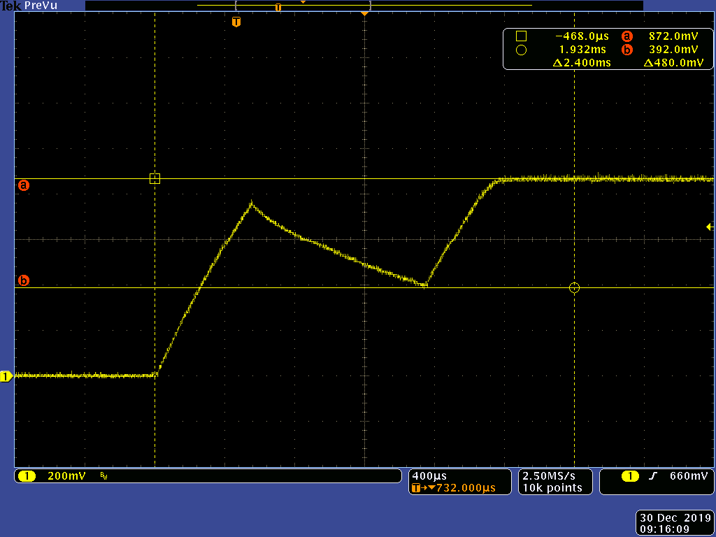
I try to set maximum load and turn-on POL, ramp up waveform are not stable.
Does this have anything to do with ripple injection? Do you have a suggested value? (for output 100uF CAP SPEC as attachment)251M4001107MR10S.pdf
Thanks,
Delun
Hi Delun,
Thanks for contacting us.We are looking for the right contact to address the query.We shall get back to you on this.
Regards,
Umayal
Hi Delun,
Could you please check the Vin and VREG waveforms together with Vout?
Yuchang
Hi Delun,
It could possibly because the soft start time is short and could be causing the device to hit current limit. As a first check, can you please increase the soft start time by changing the Rmode resistor on the TPS53353? I see there are multiple rails in the schematic. Which rail is having the issue or is it common across all rails?
Also, here is a checklist attached that you can use to review the schematics.
Regards,
GeroldTPS53353_TPS53355_Schematic_Checklist_v1.0.docx
Regards,
Gerold
Hi Delun,
Did you get a chance to try the above suggestions?
Regards,
Gerold
HI Gerold, Yuchang,
I try to adjust the soft-start, it's can be improved.
But, For VCC1V8 rail ,
Frequency will exceed 10% ,The settings I have done now are as follows,
R1391 connect to PG, and change to 49.9k.
Remove R847, C1094 and C1213.
PL1 change to 3.3uH
R1395 Change to 20.5k
R1397 change to 10k
Can you help confirm what else can be adjusted?
thanks,
Delun
Delun,
I think the issue that you are seeing is the ramp of the output voltage and the time-constant of the Ramp injection circuit (14.7k into 23nF) interacting, and the DC blocking time-constant being so fast that the ramp injection is effectively lost when the part stops switching in DCM mode.
The large ripple from the ramp injection circuit is causing the output voltage to lead well ahead of the reference voltage ramp, and when the switching stops due to Auto-skip operation under no load, the ramp injection is lost and the output voltage has to drop significantly before switching restarts.
1) Increase the Injection time-constant to reduce the injected ramp amplitude.
2) Increase the DC blocking time constant to increase the auto-skip DCM off-time that can discharge the DC blocking capacitor.
I would recommend:
Increasing R187 from 14.7kOhm to 25k (this will reduce the ripple injection)
Increasing C239 from 22nF to 47nF (this reduces the loading effect of C241)
Increase C241 from 1nF to 10nF (this will reduce the DC blocking time constant)
The reduced injected ripple will reduce the average output voltage slightly, so it might be necessary to resize R198 and R196 to get the right final output voltage, depending on the designs tolerance to DC error. With the injected ripple, I am calculating an effective FB reference voltage of 603mV. If you need help selecting R196 and 198 to achieve the desired output voltage, let me know the target output voltage and I can help you calculate the required resistors.
Peter,
Could you help to check U36 "VCC1V8" Rail ? I think the frequency of this rail changes too much.
I have changed all rails to CCM and I think it can reduce the instability.
And output 100uF CAP E.S.R.= 4 ohm /each
Vout= 1.8V / Ioout=3A
thanks,
Delun
Delun,
Anything specific on the 3 TPS53319 schematics that needs reviewing?
Can the attached circuit help to review it?
Conditions are remarked in the circuit .
Delun,
U36 is a TPS53319 schematic, so when David Daniels asked if there was anything specific about the TPS53319 designs you wanted reviewed, it would have been good to mention this frequency stability question as something you specifically wanted reviewed.
In D-CAP mode control, the frequency jitter is inversely proportional to the amount of ripple voltage at the feedback node. For 12V to 1.8V @ 300kHz, the R-C ripple see 5.1uV-s, for 3k driving 100nF, that's 17mV of ramp, which is a good amount of ripple, but the injection circuit has only 1nF driving about 667-ohms of impedance at the FB node, so the DC blocking bandwidth is 238k, to the ramp is getting attenuated and phase-shifted by the DC-blocking.
I would recommend increasing the feedback resistors R1397 and R1395 to 10k and 20k respectively to increase the feedback impedance and improve the ramp injection.
With the ramp imposing 17mV on the feedback, that's 48mV at the output voltage. With 10.8A of peak to peak inductor ripple, which is VERY high for a 3A output, it's emulated and ESR of 4.4mOhms, that's an effective ESR bandwidth of 72kHz with the nominal capacitance. With 1.8V on a 4V ceramic capacitor, that's likely not enough ramp injection to achieve frequency stability given the high capacitive ripple on the output voltage.
You can consider a larger inductor, more output capacitance, or more ripple injection to reduce the frequency jitter.
Looking over the other TPS53319 schematics:
They all appear to be using the same 300kHz switching frequency, 470nH inductor and 3.01k into 100nF ripple injection circuit with about 500uF output capacitance.
While the other TPS53319 designs have >10k feedback resistors (first issue noted in my prior response) they are all also likely suffering from the second and third issues:
1) very high inductor ripple current
2) Low Output Capacitance / Ripple Injection
So they customer may want to consider similar changes to the other TPS53319 designs as well.
Delun Koa,
For the TPS53319, all the output filters are the same. With the conditions from schematic in the webench calculates the following.
Your inductor ripple current very large, eg the 1.8V has a 10A ripple current and configured for skip operation at light currents.
The load current would need to be greater than 5A to operate in CCM.
I suggest the following changes.
12V to 1.8V 3A Change PL1 4.7uH R847 1.27k
12V to 1.105V 6A Change PL12 2.2uH R832 909
12V to 1.2V 9.5A Change PL11 1.5uH R820 845