This thread has been locked.

If you have a related question, please click the "Ask a related question" button in the top right corner. The newly created question will be automatically linked to this question.

TIDA-00386: We are looking for development of BLDC fan without remote control operation.

Part Number: TIDA-00386
Other Parts Discussed in Thread: UCC28630, DRV10987, DRV10983

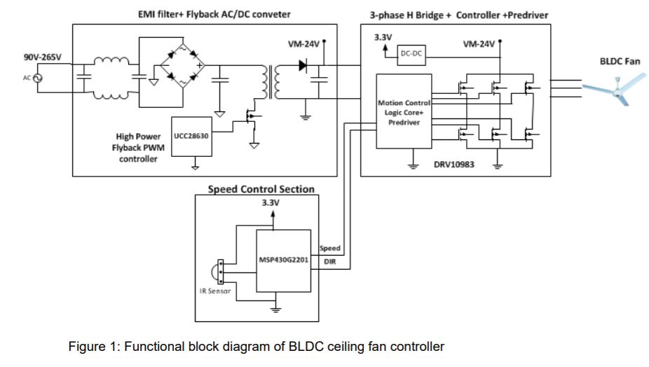
We are looking for development of BLDC fan without remote control operation. Fan speed should be regulated thru custom regulator design and it should be retrofitted in place old AC fan regulator design. Is this part is suitable to the same design what I am expecting. All the house holders may not show interest to operate with remote controllers and interested to operate with knob switch. Please provide your thoughts. Thanks

  • Giri,

    Let me check with the design owner and get back to you.

    Regards,

    -Adam

  • Hello Giri,

    Below is the block diagram of the TIDA-00386:

    It sounds like you are trying to replace an AC fan design with a 3 phase Brushless DC fan design. I am specifically in charge of the motor drive part of the block diagram and if you choose to use TI for the AC to DC regulator circuit, I encourage you to ask them questions on E2E with the specific part number (which would be UCC28630 in this design).

    The DRV10983--or DRV10987 (take a look at this document for more info: http://www.ti.com/lit/an/sloa274/sloa274.pdf)--would be perfect for the fan application.

    As shown in the block diagram, the MSP430 controlled the DIR and SPEED input pins of the DRV10983. Let's talk about these pins in a bit more detail.

    DIR:

    The DIR pin is an 3.3V digital input pin. When low, phase driving sequence is U → V → W and when high, phase driving sequence is U → W → V. This, changes the direction.

    Many customers decide if they want the DIR to be changed (which would require a switching circuit between high and low, plus some extra tuning) or fixed (where tying to GND or pulled up to V3P3 would be easily implemented). 

    SPEED:

    The SPEED pin is where the "knob switch" would make the most sense. Specifically, the SPEED pin can be configured to accept a PWM or analog voltage. When the PWM is configured, it will take duty cycle as the percentage of speed (where 0% is off and 100% is maximum speed, more details in the datasheet section: Digital PWM Input Mode Speed Control). When the analog voltage is configured, a percentage of ~3.3V will determine the speed command (where GND is off and 3.3V is max speed, more details in the datasheet section: Analog Mode Speed Control).

    Because you said knob, it sounds like a potentiometer run off V3P3 (or 3.3V), when the device is configured for an analog input, might be the best way to control the speed.

    Best,

    -Cole