This thread has been locked.
If you have a related question, please click the "Ask a related question" button in the top right corner. The newly created question will be automatically linked to this question.
Tool/software: WEBENCH® Design Tools
Hi experts,
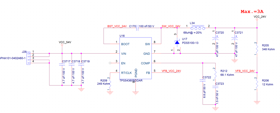
The schematic RLC value are reference from TI WEBENCH
Input 52 to 56V with 3A output
we have modified the RLC value in EVM board with our design
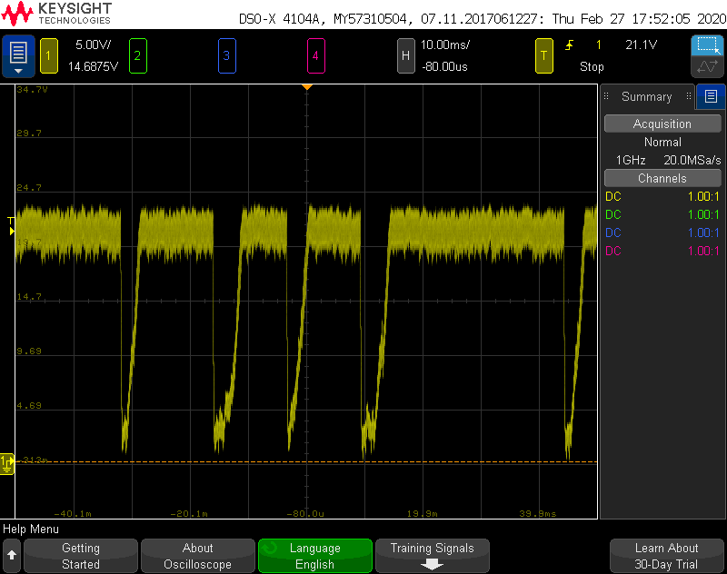
when loaded with 1A current, the inductor has obviously noise
after increase fequency (RTCLK = 162k), loaded with 2A current, the inductor also has obviously noise
do you have any comment for this issue?
Hi Jeremy Gu,
Could you please share the below details on this query.?
1. Please share the input/output conditions. VinMin, VoutMax, Vout, Iout, Frequency?
2. Please share the WEBENCH design you are referring to using the ' Share Design' option.
3. Please confirm if you are referring to the SLVU769B EVM design.
4. Kindly share the schematic and results(IL, Vout, Vin) of your modified design for both the load currents(2A & 1A).
Thanks & Regards,
Praveen
Hi Praveen.
1. 52~56 input, 24V output with 3A, frequency is 391.45KHz
2. FYR
https://webench.ti.com/appinfo/webench/scripts/SDP.cgi?ID=6D9E9161919B7256
3. Yes, we are used SLVU769B EVM and change RLC value for our design
4. Vout is 24V and Vin is 54V for 1A and 2A load
When RT/CLK is 249K ohm, loading with 1A has obviously noise
When RT/CLK is 162K ohm, loading with 2A has obviously noise
Thanks
Hi Jeremy Gu,
We have forwarded your query to the concerned team. We will get back to you shortly.
Thanks & Regards,
Praveen
Jeremy,
Can you please explain what you mean by obviously noise? Please share a waveform so we can help diagnose this issue.
Thanks,
-Sam
Jeremy,
Please share waveforms showing SW and VOUT. Audible noise usually means instability.
Does the circuit have noise when operated at a lower output current?
-Sam
Jeremy,
Earlier you said the inductor had audible noise at 1A or 2A depending on switching frequency. Now you say it doesn't have noise up to 2.5A. What has changed in the design?
How are you measuring the switch node? That measurement looks very noisy. Are you using the tip-and-barrel method?
The switch node does look unstable. It should be operating at a constant frequency.
When you say you changed RLC value, do you mean you've updated every component including the compensation network?
-Sam
Hello Jeremy,
Can we get insights on your debug process by answering Sam's questions outlined in above post?
Please let us know if this issue has been resolved. We will waiting to further assist.
Jeremy,
I see that VOUT is collapsing. From the waveforms shown over email, VOUT has large ripple with increases with load (~1.2VP-P at 500mAOUT, ~3.2VP-P at 1.5AOUT, and the waveform you showed above at 2.6AOUT.)
Simulations show that the design is stable. This makes me think there may be an issue with the layout. Please share the layout and I will review.
Thanks,
-Sam
Hi Sam,
Jeremy used the TPS65360EVM-182 and replace all the passive components (RLC) on board with their passive components which are suggested in WEBENCH. So layout may not be a problem because they used the EVM board. DO you have any suggestion about the issue?
Roy
Roy,
You're correct, the EVM has a good layout so your issue is probably not layout related, unless components had to be moved when you changed component values. Let me know if there were any major changes.
Is the IC getting very hot? Does this issue occur at a lower current at a hotter temperature?
Please try lifting one pad of the inductor and adding a loop for a current probe. I'd like to see the inductor current waveform with the switch node.
-Sam
Sam,
The major changes is inductor=68uH and output voltage=24V(feedback resistor). We check the inductor current could support up to 6A. The issue occur at higher output current(2.5A). (inductor has noise at output current higher than 1.5A)
We will check inductor current from switching node.
Regards,
. (inductor has noise at output current higher than 1.5A)
We will check inductor current from switching node.
Regards,
Roy
Roy,
Thank you for that information. Please attach the waveforms of inductor current and switch node when you have them.
-Sam