This thread has been locked.

If you have a related question, please click the "Ask a related question" button in the top right corner. The newly created question will be automatically linked to this question.

TIDA-01371: The pull current of a capacitive load from a pulsed source

Part Number: TIDA-01371

Hello Sanjay

I followed your TIDA-01371 design and went through documents tiduci3a and “Driving High-Voltage Piezo sensors without using Big Capacitor banks Part-1” more than once. However, I am still confused by the calculation of the piezo current when it is driven by a pulsed source. Here is a list of questions. I wish you could pay attention to them and answer them. Your advice is highly expected and appreciated.

1.     What attribute of current do we care for the sake of enough energy stored in the capacitor bank?

The transient current at the initial pulses of a pulse train? assuming the capacitive load has zero energy storage before the pulser starts to work.

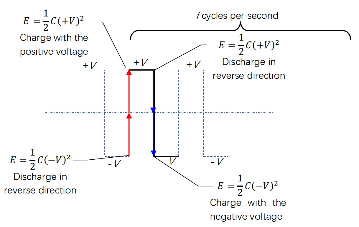
The transient current at each transition between a positive high voltage level and the negative one? a.k.a. the discharging of a capacitive load when the drive voltage flips its polarity

The steady current after initial pulses in a pulse train ?It will become the fundamental wave eventually

The averaged steady current? e.g. the RMS value?

The fundamental component of the rectangular pulse in its Fourier expansion

The odd order higher harmonic components, such as THD?

2.     Two formulas were cited in those 2 documents are hard to be understood.

In “Driving High-Voltage Piezo sensors without using Big Capacitor banks Part-1”, the formulas are

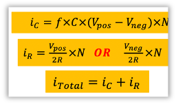
We know the sinusoid current through a capacitor can be calculated in this way

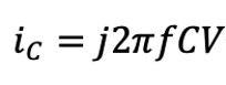
If the voltage V in the equation above represents the amplitude of the fundamental component of the rectangular pulse in its Fourier expansion, iC is the fundamental current which has the same repletion frequency as the rectangular pulse.

However, Vpos-Vneg, is employed in the document. What is the meaning behind?

If the driving rectangular pulse has no duty-off time. Both its positive half cycle and the negative one will make the same current Vpos/R= -Vneg/R in a shunt resistor, except their opposite directions.

However, Vpos/(2R) or Vneg/(2R) is used in the document. What is the reason behind?

The ultrasound probe cited in the document does not provide its input resistance. Is this the reason that iR is dropped in the following equation derivation?

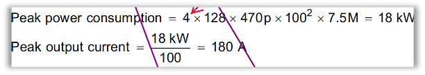
In the following equation derivation, instead of the equation of ic, the input current if a transducer is concluded from the estimation of input power.

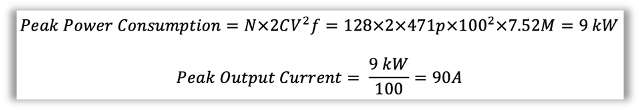
As we know an ideal capacitor does consume power but store and release power with a circuit. The Vpos = -Vneg=100V will not deliver that much power to a capacitor. So, what is the reason of this equation of power consumption?

In documents tiduci3a the power consumption is doubled, why?

3.      Matched load at a resonant frequency

If every piezo element in an array is matched to 50Ω at the resonant frequency, shall we use 50Ω to estimate the steady input current of a transducer?

4.      Not all transducer manufacture provides the capacitance of their transducer, how do we apply the power design in this scenario?

Best Regards!

Wallace 


  • Hello Wallace,

    Thank you for reaching out. I will review your questions and get back to you with answers within 1-2 days. Thank you for your patience.

    Regards,

    Sanjay R. Pithadia

  • Hello Wallace,

    First of all, I apologize for the delay in replying to this thread. Please find the answers to your questions below:

    1. For the capacitor bank, the energy depends on the transient current at the initial pulses of the pulse train, each transition between a positive and negative high voltage and average steady state current. 

    2. The current is dependent on total voltage applied to the transducer. We are assuming positive high voltage and negative high voltage here. So the total voltage applied to the capacitor will be Vpos – Vneg as highlighted in the formula. 

      The term two is included in resistor current calculation, because the drive signal pulses have 50% duty cycle. 

      The focus of the presentation was to show the calculations of power into capacitors, which is why resistor power is not considered. However, it will be constant power and should be added to the total power consumption. 

      I am adding a power-calculation.pdf which we prepared. You will get clarifications in that document. 

    3. I doubt, if you have matched load at such high frequency. But if you have it, you can use the matched impedance to estimate the steady input current of a transducer. 

    4. Typical value of the transducer capacitance is from 220pF to 470pF. You need this value for the calculations. All transducers have it, please ask for it. 

    I have a few questions for you:

    1. What is the application you are working on?

    2. Can you please share details of transducer, driving waveform and other details of your application?

    3. Does it need capacitance bank? If yes, what value are you using?

    Regards,

    Sanjay R. Pithadia

  • Hi Sanjay,

    Thank you for your reply in detail!

    Most of your answers make sense to me, except the concept of " the power deliver to a capacitor".

    I believe it is a common sense that an ideal capacitor won't consume power, but store and exchange it with the circuit.

    Maybe, it is an equivalent trick to handle a capacitive load, isn't it?

    Would you please recommend any reference paper or book that I can learn such method of "the power deliver to a capacitor" ?

    Here are my answers to your questions.

    1. A ultrasound scanner for medical applications is what I am working on;

    2. The transducer what I am using is an ordinary one. It came without the specification of capacitance, but a resonant frequency.

    3. I think a capacitor bank is needed. That is why I try to figure out how much capacitance is enough to serve specific ultrasound pulse sequences with a specific transducer array.

    Best Regards!

    Wallace


  • Hello Wallace,

    Thank you for the answers. You may not find much material about "power delivered to capacitor" but you can find good material on internet for "Energy stored in capacitor". I am attaching couple of links for you to refer:

    https://www.dummies.com/education/science/science-electronics/find-the-power-and-energy-of-a-capacitor/

    http://hyperphysics.phy-astr.gsu.edu/hbase/electric/capeng2.html

    Regards,

    Sanjay R. Pithadia

  • Hi Sanjay,

    Thank you for the reply. 

    I guess the repeated energy stored and discharged from the capacitive load is the key to derive your formula in tiduci3a.

    Here, I prepare a chart to depict the charge/discharge process under a pulsed source.

    Let’s assume the driving pulse swings between +V and -V at a frequency of f and the capacitance of a capacitive load is C.

    The stored energy in C is 1/2*C*V2 at both +V and -V.

    When the driving pulse flip its output from -V to +V, ie. the rising edde, the positive voltage source will be involved in energy transfer in 2 stages, which are highlighted by 2 red arrows in the chart.

    Stage 1. The stored energy 1/2*C*(-V)2 with a reversed polarity leaks and capacitor voltage returns to 0.

    Stage 2. The energy of 1/2*C*(+V)2 is built by the positive voltage source during the charging session.

    So, in total, the amount of C*V2 energy is transferred at the rising edge of the driving pulse.

    On the contrary, the negative voltage source is involved in the energy transfer of C*V2 at the falling edge of the driving pulse, indicated by 2 blue arrows.

    In 1 second, f times rising edge and also f times of falling edge happen. So, the power of energy transfer is C*V2*f for either the positive or the negative voltage sources.

    In the end, the equivalent power related either positive or negative voltage source is C*V2*f, instead of 4*C*V2*f, which is derived in your manuscript and  tiduci3a.

    Could you see and problem in above derivation?

    Best Regards!

    Wallace

  • Hi Wallace,

    The calculations look good to me. We will revise our document after internal discussions, Thank you.

    Regards,

    Sanjay R. Pithadia