Tool/software: WEBENCH® Design Tools
I have used the work bench to create work bench with inuts of
Vin min : 24V
Vin max : 30V
Vout ; 24V
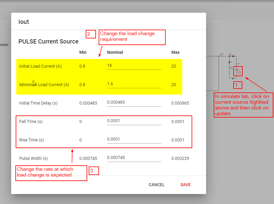
Iout: 16A
I see two mosfets in parallel on the top part of the H bridge, why is there unequal distribution and can it be replaced by one big mosfet.