A related question is a question created from another question. When the related question is created, it will be automatically linked to the original question.
If you have a related question, please click the "Ask a related question" button in the top right corner. The newly created question will be automatically linked to this question.
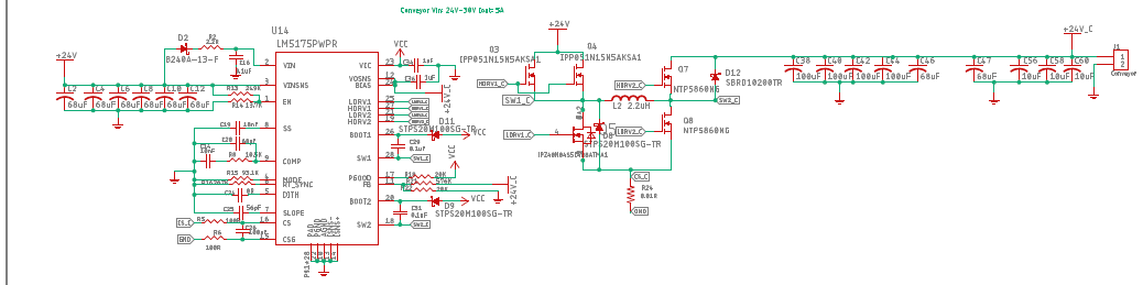
From the first glance on the schematic, I cannot see anything obviously wrong. It is hard to read the values, so could you please send a higher resolution picture?
Please check if all components are soldered properly and correct, sometimes diodes or electrolytic caps are easily reversed.
Please check the input and output voltage, as well as the inductor current. It is possible that instability in voltage or current causes the excessive heat.
What input voltage range do you have in your system and what is the maximum output current? BTW, for 100kHz, the inductor value is very small. You might increase it to 10uH or 15uH. Or you reduce the value of the RT resistor to increase the switching frequency.
I wonder why the output voltage is not stable to 24V, after the load with min current consumption is connected. Even after the Feedback resister is fixed for 24V. Can you help us with this issue