This thread has been locked.

If you have a related question, please click the "Ask a related question" button in the top right corner. The newly created question will be automatically linked to this question.

PMP9738: How to conclude 200A/255A are continous/peak current rating for this design?

Part Number: PMP9738

Hi expert,

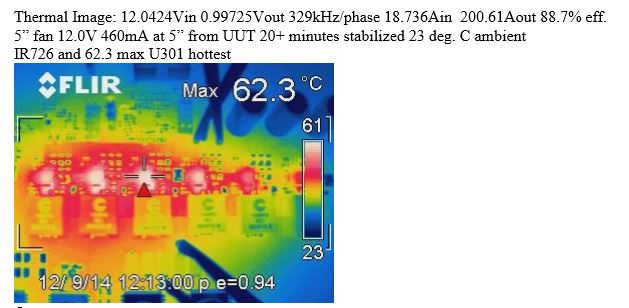
From the thermal image, I didn't see any concerns about 200A output, it seems higher continous current can be achieved, right?

So would like to know why we mark 200A for current rating in this design?

Also, why 255A is the peak current rating? Any protection will be triggered or any other consideration?

  • Hello Sir,

    basically it's a six phase design and each power stage is able to handle up to 60A continuous;
    the inductor windings are rated for 68Arms, the core is rated for 80Apk at 25c and 68Apk at 125c.

    So at the end the design is doing good for 240A continuous - if the thermal interface fits !
    Beside current stress analysis a thermal analysis is needed for your design, depending on:
    - ambient temperature range
    - copper area around power stages to sink the heat, copper thickness, number of layers
    - convectional cooling or forced cooling; if so, how many m/s

    Means - providing a perfect thermal interface results in high current capability;
    that's why we show the thermal image in our test reports. Upper text explains that the image has been
    taken by using forced cooling, dT around +40K at an output current of 200A.

    Best regards, Bernd

  • Thanks for your explainations, could I have a rough concept of range, about how much current one phase can handle in actual bench, with regular thermal environment?

    Just from this design condition, it seems one phase can output up to 240/6=40A, right?

  • Hello Sir,

    please look at the detailed test report, this individual PCB handles

    - 120Aout, convectional cooling, at a temperature rise around +40K
    - 200Aout, forced cooling, at a temperature rise around +40K

    "Regular" thermal environment needs to be specified, let's assume -40c up to 85c,
    so at forced cooling and 200A load expect this individual PCB to be at 125c.

    Operating that high might impact MTBF, so reliability.
    Btw, +85c would be fairly high for any server application.

    You need to specify operating temperature range, convectional cooling or forced cooling;
    if forced cooling, how many m/s.
    Furthermore for server applications you need to differ in between average current and peak current;
    cores are not loaded 100% by calculating power. For thermal interface the AVERAGE current is the
    design parameter.

    Just regarding your upper current stress each power stage and each inductor is able to handle up to
    60Apeak. Regarding continuous loading power sharing needs to be considered, PCB needs to be
    considered and thermal interface/ambient temperature needs to be considered.

    Best regards, Bernd