This thread has been locked.

If you have a related question, please click the "Ask a related question" button in the top right corner. The newly created question will be automatically linked to this question.

TIDA-01486: TIDA-01486 for amplification of driving power

Part Number: TIDA-01486
Other Parts Discussed in Thread: EVM430-FR6047, , MSP430FR6047, TS5A3357, THS3095

Hello,

I use the EVM430-FR6047 for ultrasonic volume flow measurement and the TIDA-01486 reference design. 

After connecting the TIDA-01486 to the EVM430-FR6047, no receiving signal is detected by the EVM430-FR6047. In parallel I can measure the receiving signal with an Oscilloscope direct at the receiving sensor. After checking the single components, I saw that the receiving signal is smoothed out after the capacitor of the PZT connector. 


The capacity of my sensor is approx. 1600 pF. Is there a way to change components and not smoothing out the signal?

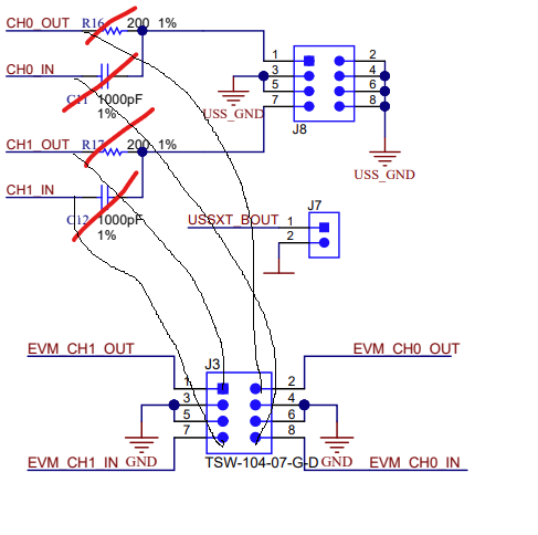
Since we don't need the OP amplifier, we thought about connecting the response directly to the EVM.

  • Hello,

    How are you connecting J3 from the TIDA-01486 to J8 from the EVM430-FR6047? Keep in mind that CH0_OUT, CH0_IN and CH1_OUT, CH1_OUT goes to the same pins in the J8 connector respectively pin 1 and pin 7 while in the TIDA-01486 they are separated so you need to use accordingly blue wires to make sure to keep these channels split. 

    At which frequency is your PZT resonating?

    Thanks

    Giovanni

  • Hello Giovanni,

    We connected both boards as sketched in the picture below. We removed R16/16 and C11/12 and connected both boards. Also a picture of the board is attached.

    The receiving signal can also be measured directly at the pin of J4. I only use 2 transducers. Attached is also a picture of the Oscilloscope. You can see the excitation signal and the according response. Both measured and the pins of J4.

    The resonant frequency of the piezo is 1 MHz.

  • Hello,

    Boards seem connected correctly. The receiving chain of the TIDA-01486 has been designed for a specific pipe diameter and PZT as explained in the user guide in the Section 3.2. 

    I would suggest to play around with the gain of the amplifier or reduce the gain of the MSP430 via the GUI. Potentially as you mentioned and if not needed you could also bypass the amplifiers.

    Hope this helps. 

    Let me know if you need any additional questions,

    Giovanni

  • Hello Giovanni,

    I use the "Original" TIDA-01486 reference design with a Gain of 10. Since I use a selfmade clamp-on design with Piezo discs the Gain seemed to fit well for excitation. 

    Are there any experiences with clamp-on designs for the gain?

    I already adjusted the gain of the MSP430 to the minimum. The ADC value decreases but still no signal exists. 

    Additional questions: 1) The driving voltage for the amplifiers now is +-12V. Could that cause problems as well?

    2) At the EVM_CHx_IN we measured an DC offset which should not be there, right? I was wondering, because in another thread was mentioned that the capacitor C11 and C12 on the EVM430 should be removed. 

    3) We have on EVM430 board available without the splitting of the out and in channels. Here the ADC seems to have some defect, but could the missing capacitor on the EVM cause problems? I could also try to split the in and out channels but keep the capacitor C11 and C12 on the board. I will not be able to see any ADC signal, but could measure the signal with an Oscilloscope to see what happens. 

    4) Do you have some tips how to make the transducers and the TIDA-01486 fit together? 

  • Hello,

    We have only done measurements with in-line transducers and not clamp-on ones. I would expect a higher gain needed when clamp-on transducers are used.

    What is the maximum voltage accepted by your transducers? In our test the transmit signal was lowered to ±6.6 V by amplifying only by 2 the signal coming from the MSP430FR6047 MCU.

    At the receiving signal, a 750-mV bias voltage is needed to cover the full range of the MSP430FR6047 MCU. The bias voltage is generated by the resistor divider at the non-inverting input of the THS3095. Putting a DC bias on the output of the amplifier allows the use of a regular single-supply MUX like the TS5A3357 . Have you put a jumper on J6 connector from Vb to +3.3V?

    Regarding on how to fit the transducers and the TIDA-01486 together, it really depends on the type of transducer. I would not see any problems as far as the right connector is used.

    Thanks

    Gio

  • Hello Giovanni,

    The max voltage allowed for the piezo discs is much higher than 15V, but also with these lower voltages they work fine. In tests done before the performance of the piezo-discs with the EVM alone was good.

    The jumper is placed. I thought about using an external voltage supply, but i don't really expect to change anything by it.

    I just experienced something else: 

    When only connecting one EVM_CHx_OUT to the TIDA everything works perfect. So I'm quite confused. 
    Could it be possible that the OP work then in an unstable area? Would it be stabilizing if the amplification on receiving stage is reduced?

  • Hello,

    I would suggest that you run the simulation based on the PZT that you are using. Please refer to the simulation file already in the reference design page. You would need to change only the PZT model based on the one you are using.

     Thanks

    Giovanni