This thread has been locked.

If you have a related question, please click the "Ask a related question" button in the top right corner. The newly created question will be automatically linked to this question.

TIDA-060008: Not seeing any A/B output from RS485 Transceiver

Part Number: TIDA-060008

I have followed the TIDA-060008 reference design to make a simple, but isolation protected RS232 to RS485 board.  However, I am seeing no output from the A or B on the RS485 Transciever.  I do see signal on the OUTC (Pin 5) of the Isolator to the input of the RS485 Transceiver.  I'm a bit confused about the use of the Multivibrator, and what DIN1 and DIN2 would be used for.

I am assuming that the RS485 device that I am trying to communicate with is Full Duplex.

Maybe there is a simpler circuit design out there than this, but I have this design in hand now.

Any help would be appreciated.  

  • Just some added info.

    I verified with the supplier that I am trying to talk to a half-duplex device on the 485 bus.

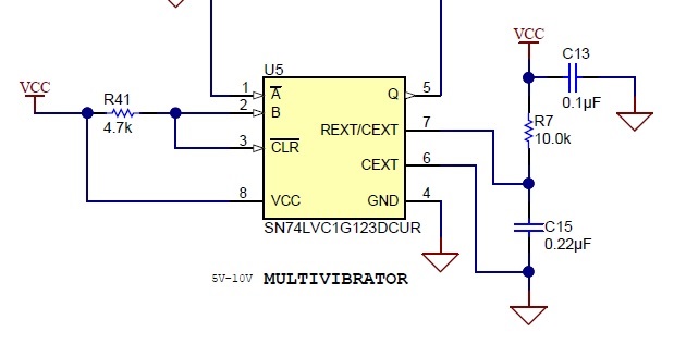
    Also, I learned that the REB_DE line is always low.  If I artificially pull it High, which allows me to then pass Transmit data through the RS485 Transceiver.  So, it appears maybe something is up with the SN74LVC1G123DCUR (Multivibrator) circuit.  R and C values look good, but Just not seeing the REB_DE line change states.

  • David,

    The multivibrator is used for direction control. The similar idea can be found in this TI design.

    www.ti.com/.../tidubw6.pdf

    This design only works half duplex (one way communication of a time). If you want to implement full duplex, you need two RS-485 chips.

    If you still cannot get the multivibrator work, can you capture some waveforms of A bar, REXT/CEXT, Q? I will try to debug.

    Regards,

    Hao

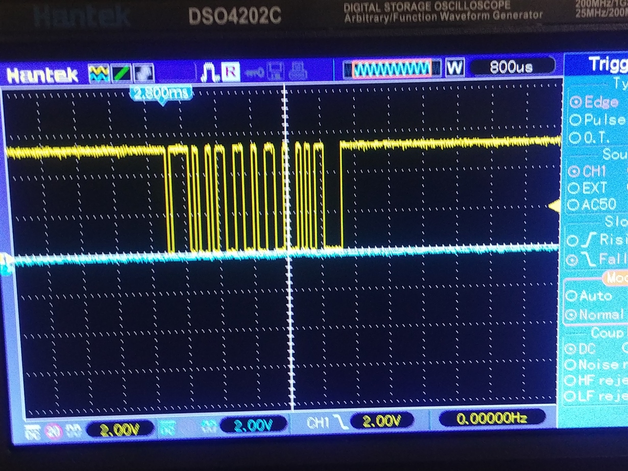
  • Abar and Q on top

    Abar and REXT below.

  • I'm not sure why the REXT wasn't being discharged at all. The circuit is triggered by the falling edge of Abar. Can you double check your schematic? Figure 4-8 of this app note shows the same setup and has discussion on the component selection. To debug the device, you can test it as the datasheet specification (section 6.6) to see if the timing in your measurement aligns with the values in the datasheet.

    Regards,

    Hao  

  • Hao,

    Thank you for your help.  I have triple checked my diagram and it appears identical to the circuit diagram.  My layout isn't exactly as in the reference design, but caps and resistors are in similar proximity to devices.

    I checked the resistors with an Ohm meter and verified their values are correct.  I guess it is possible that the PCB house populated the wrong Caps maybe, but I would have to carefully take one of my 5 boards apart to measure the caps out of circuit to get a good reading to validate their values.  I have extra boards to do this with.  As far as the pulse length testing, I'm not clear how to proceed with that.  I simply used the same R7/C13 values as in the reference design.

  • Ahh Haa.  I may have found the issue.  Pin-6 did not get filled to GND on the fill, so it is floating.

    I will jump and retest.

  • Good to know. But the pin is floating in the diagram in the app note. I have never tried this way myself though.