This thread has been locked.

If you have a related question, please click the "Ask a related question" button in the top right corner. The newly created question will be automatically linked to this question.

LP-CC2652RB: Tx Power is lower than setting

Part Number: LP-CC2652RB
Other Parts Discussed in Thread: CC2652RB

Dear Ti:

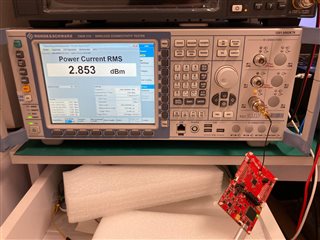
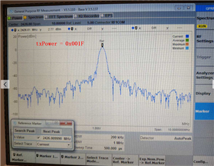
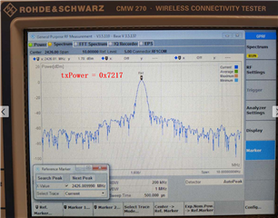
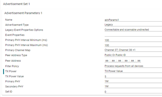
We tested the tx power about the BLE advertisement, but the results is far below than the setting(Setting is 5dbm but measure result is 2.5dbm).

(And we already tested other platform, the result is same with setting, so the tools and method seems no problem)

The measure way is same as document Measuring CC13xx and CC26xx current consumption (Rev. D) and platform as below:

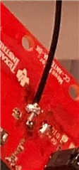
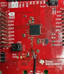
Board: CC2652 Development Kit

example: D:\ti\simplelink_cc13x2_26x2_sdk_4_30_00_54\examples\rtos\CC2652RB_LAUNCHXL\ble5stack\simple_peripheral_oad_onchip\tirtos\ccs 
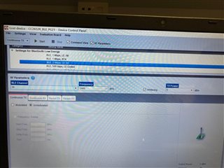
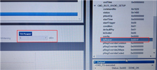
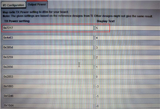
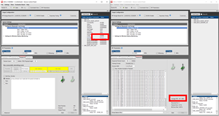
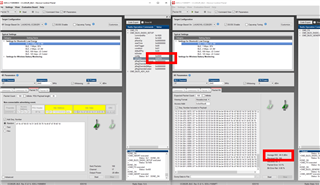
Setting as below:

So we want to check some things as below about this question:

1. Why the real tx power is lower than setting? How to improve it?

2. Is there any other setting need for change the tx power?

So many thanks to you and have a good day!

  • Hello,

    As you may have noticed, I've split this reply on your original thread to a separate thread. They are both related to power measurements, however, the questions are slightly different so I felt it was best to split the threads.

    Do you see similar results if you use the latest SDK? I've assigned this post to a colleague to comment on.

  • Hi,

    The settings look fine to me.

    The TX Power figure of 5 dBm is for the Carrier Wave at 2.4 GHz. I'm not sure how you're measuring 2.5 dBm, but I'd expect to see at least a 5-10 dB drop from the peak carrier wave output power to the peak modulated wave output power because the power gets spread over a larger bandwidth.

    If you're concerned the issue is with the hardware, I'd recommend measuring with SmartRF Studio, broadcasting an unmodulated carrier wave at 2440 MHz, and measuring the conducted power with a pigtail soldered directly to the PCB trace. This should yield a peak output power of 5 dBm.

    Best,

    Nate

  • Hi,

    We have test again as your advice, the result as below(including SmartRF Studio's setting and connect device by wire):

    As we can see, the txpower is lower than setting more than 2 dbm.

    Do you have any other advice for the result?

    Thanks!

  • Hi,

    I have some questions when I test txpower by SmartRF Studio tools:

    Above picture is the default setting when the SmartRF Studio opened.

    I want to know what's the meaning of "Tx Power(5)" and "txPower(0x001F)".

    After I change "Tx Power" to 0 and reset to 5, the "txPower" value is 0x7217, why different with before(0x001F)?

    BTW, I find the mapping table as below(if it is):

    If this is the mapping table, why the default setting is NOT correct when I just open SmartRF Studio?

    Thanks!

  • Hi Junde, 

    A few thoughts:

    1. Can you measure at 2440 or 2400 MHz? Our amplifier is known to exhibit a small amount (less than 1 dB) of loss at the higher end of the 2.4 GHz band.

    2. Have you de-embedded your line? I could very easily see 1-2 dB of loss from the connection you have between your board and the spectrum analyzer because the wire looks flimsy. If you've measured 5 dBm with a different device, then you can disprove this theory by measuring 5 dBm with a similar wire of a similar length on a different device. 

  • If you have an unrelated question as you do above, I would ask that you open a new thread to ask it so we can best assist you and others who will browse these forums in the future. Thank you!

  • I think it's related question for checking txpower by SmartRF Studio, it's your advice above.

    Can you guide me is there any wrong setting in smartRF's UI?

    And give us some advice for those question above?

    so many greeting to you!

  • The wire is OK, we test nordic's board as the same way.

    And we measure at 2400 and 2440 MHz too, the result is NOT good.

  • Ok great I'm glad you were able to isolate the issue!

    What version of SmartRF Studio are you using? Is it the newest? (1.8.2) When I open SmartRF, I just see the 0x7217 value. The 0x7217 value in the TX Power Register is the correct one too. So, I would recommend repeating your test with the 0x7217 value if you haven't already. Let me know your results.

    If you want to learn more about the TXPower register, see page 36 in the datasheet.

    I don't have access to a spectrum analyzer right now, but I have run the following test: If I place the launchpads less than 1 m apart and don't move them from one experiment to the next, I don't see a great change in power if I change the TXPower register from 0x7217 to 0x001F. I do see an approx. 25 dBm difference in power from the 5 dBm to the -20 dBm setting though. I am comfortable attributing the 1 dB improvement from 0x7217 to 0x001F to error (I ran it multiple times and saw about 1 dB of variation each trial, but only show one screenshot below).

    0x7217 (5 dBm setting)

    0x001F(Undefined setting)

    0x04C6 (-20 dBm setting)

  • Thank you!

    your results have some similarity with mine(the 0x001F's result always higher than 0x7217).


    And our smartRF version is 2.20.0 ?

    Thanks for your reply!

  • Hi,

    Apologies about earlier - I collected the results on version 2.21, but there is an even newer version (2.22) that I would recommend using.

    However, I don't think it's likely to be a SmartRF Issue because you're seeing the same performance with SmartRF Studio as with CCS.

    I do wonder about your launchpad connection though. From the picture you sent me, it looks like you've soldered your measurement line on the path with the JSC connector. It looks like a decent soldering connection, but I can't confirm without a clear photo. Can you send a photo of the connection in focus? I'm wondering if potentially you're only drawing some of the power due to a parallel connection left in place or something similar. Essentially the photo below but in greater detail.

  • Hi,

    Thank you for your observation so carefully.

    I take the picture as below, actually we have many kits for measuring, however we don't have the antenna with the same connector, the results is always same. And we also have some nordic's board with antenna by soldering and the txpower results is more than 4 dbm.

  • Thank you for the picture. I see your issue now.

    Notice how on your board, in the RF path, power travels from the IC through the Balun to the pigtail you've soldered on. But, there's a parallel path after the pigtail that leads to the JSC connector on the board. This parallel path acts as a stub and degrades your antenna match. If you're going to mesure this way, I'd recommend desoldering the blocking capacitor next to your pigtail, and soldering the pigtail onto the pad to the left. This will get rid of the stubs you're creating and allow for a good measurement.