


Other Parts Discussed in Thread: BLE-STACK, AM3352
Hi Expert,
I am communicating with the CPU and BLE Module, but I have confirmed that the SRDY signal during continuous communication from BLE does not meet the timing requirements for continuous communication from the slave described in the NPI User Guide. The details are as follows.
<Communication conditions>
-Method: Network Processor Interface
-Master: CPU (AM3352bzcz)
-Slave: BLE module (CC2650MODA)
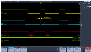
<High time of SRDY signal>
-NPI User Guide Requirement: 270usmin
-Measured value: about 66us to 90us
The software for the BLE module uses the following provided by TI.
SDK version: BLE-Stack 2.2.7 (folder name: ble_sdk_2_02_07_06)
Project: \ble_sdk_2_02_07_06\examples\cc2650bp\simple_np
Where should I modify the TI supplied software to meet the timing requirements?
Thanks
Sakai

