This thread has been locked.

If you have a related question, please click the "Ask a related question" button in the top right corner. The newly created question will be automatically linked to this question.

CC2340R5-Q1: About matching in CC2340R5-Q1

Part Number: CC2340R5-Q1
Other Parts Discussed in Thread: CC2340R5

Tool/software:

Hi TI team

   Would you mind sharing us the best maching in CC2340R5-Q1 RF design?

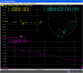
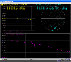
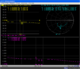
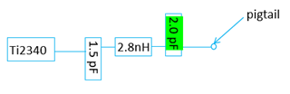
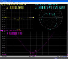
   One thing we confuse, We use default matching(from chip 1.5pF 2.8nH 1.5pF), which is the same as TI 2340R5 RF design, and we get S11 as below picture:

When power up DUT without sending cmd and get S11 Smith:                      When power up DUT with sending RX cmd 01 1d 20 01 00, S11 Smith:                                 


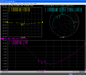
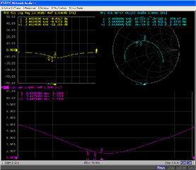
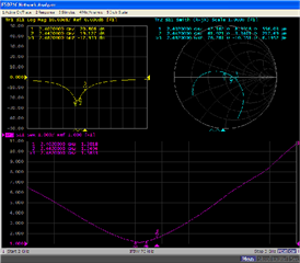
Later, We tuned matching(from chip 1.5pF 2.8nH 2.0pF), which is more close to center of smith, and we get S11 as below picture:

When power up DUT without sending cmd and get S11 Smith:                      When power up DUT with sending RX cmd 01 1d 20 01 00, S11 Smith: 


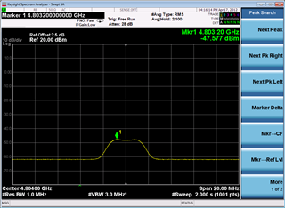
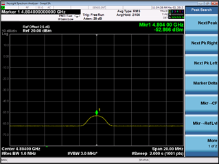
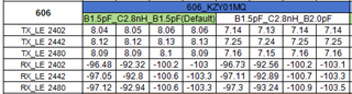
Then we use IQfact+ to test RF performence, we found power of maching1(1.5pF 2.8nH 1.5pF) is better than Maching2(1.5pF 2.8nH 2.0pF), but the sensitivity is almost same:

Now we want to ask you to learn whiching matching is better? And in Smith about CC2340R5-Q1, where is the best location for the matching in CC2340R5-Q1 RF design? 

Our antenna Matching is almost in center of Smith. We also confuse that if we want get the best power in TRP, How can we tune Front-end matching in RF design, based on TX mode matching or RX mode matching?

In a word, How can wetune Front-end matching, in order to get best performence, in the case of Antenna matching is OK?

Best Regards,

Annie

  • Annie,

    Looping in an expert from the team to assist you. The match will almost always be different on your specific hardware than what we use on our LaunchPad as this is dependent on the antenna used, trace length of the RF, component variation, form factor etc. It's also recommended that the match be done with the final enclosure. That said, the S11 measurements with the match with 1.5pF 2.8nH 2.0pF looks much better than the first. I think there is still room for improvement and a team member will help assist further. 

    Also recommend reviewing this app note: www.ti.com/.../swra726.pdf

  • Hi Annie,

    The target impedance for CC2340 is 50 ohm. The three passive components are there for filtering the harmonics. When it comes to matching, there are often a trade of between matching for the optimum sensitivity, output power, current consumption and harmonics.. The optimum point for one parameter is often different from the optimum point for another parameter. That is why it is important to look at all of these parameters when you try are try to match. The match could also be different between two different designs, pcb stackups, component sizes etc. as Evan has already mentioned.

    Have you looked at the harmonics? Might be that the level of the harmonics are high for Maching2 compared to Matching1 and more power is going to the harmonics instead of the wanted signal. That could be the reason for the lower output power for Matching2. 

    Best regards,

    HG

  • Hi HG,

         Thanks for your help.

         'The target impedance for CC2340R5 is 50 ohm.' -It means from cc2340R5 without three passive components , the impedance is already 50 Ohm? Is it power up CC2340R5 to see the impedance? Or Just to see the impedance no power up? But if we add three passive components to restrain the harmonic, may be the impedance will be changed? We are afraid that Fronted-matching is not well matched with Antenna. Because our Antenna matching is 50 Ohm now.

        And For matching2, I will check Harmonic later.

        And in the way I tune the matching, it is based on TX mode is better or RX mode? As you can see in the picture, in RX mode, S11 seems to more close to the 50 Ohm, TX mode is farther with 50 Ohm.

        Maybe I need to check the impedance of LPEM CC2340.

        More detail I will feedback in June 11th, we are on Dragon Boat Festival.

    Best Regards,

    Annie

  • Hi Evan,

         Thanks for your propose, and HG also respond to me, I will talk more detail with him after Dragon Boat Festival.

    Best Regards,

    Annie

  • Hi HG,

        I have retest harmonic in 2402MHz, comparing with matching1 1.5pF 2.8nH 1.5pF, the harmonic of matching2 1.5pF 2.8nH 2.0pF is lower.

    Harmonic(signal:2402MHz) of matching1 1.5pF 2.8nH 1.5pF         Harmonic(signal:2402MHz) of matching1 1.5pF 2.8nH 2.0pF


    And about default matching from TI2340R5-Q1 with The three passive components.

    I have do the calibration for Coaxial wire in Vector Network Analyzer. My test result as below:

    without power up dut only from chip

    TX mode with power up dut                                           RX mode with power up dut, cmd: 01 1d 20 01 00


    Maybe I haven't understand the first sentence you talk, If you have more ideas about the fronted-matching, please let us know, thanks.

    Best Regards,

    Annie