CC2340R2: LFCLKGOOD set regardless of crystal state

Expert 3250 points
Part Number: CC2340R2

Tool/software:

Hi team,

My customer is having a crystal-related issue.

What they are trying to do

They are developing test code for the CC2340 that will only be programmed and used in the lab to test the CC2340 crystals' startup time and accuracy.
The strategy is to:
  • ensure the internal oscillator is off
  • route the crystal signal to DIO12 for a buffered output
  • set a GPIO (DIO20) high
  • enable the external crystal
  • set DIO20 low when the appropriate flag indicates that the crystal is good
  • measure pulse width of DIO20 for startup time
  • measure frequency on DIO12
What works so far
The implementation for the 48MHz crystal seems to work as expected.
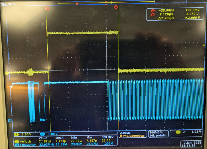
In the plot below (CH1 is the startup up time pulse, CH2 is the buffered crystal output), you can see the startup pulse go high, then the clock signal appears, then the startup pulse goes low indicating the crystal "good" flag was set. In this case, startup time was 7.208us.
For the 48MHz crystal, we use the HFXTGOOD flag.
flag.
Also, for the 32KHz implementation, the buffered clock output on DIO12 is working as expected


What is not working
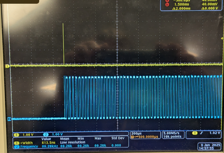
For the 32KHz implementation, they use the LFCLKGOOD flag. The LFCLKGOOD flag uses the configuration in LFQUALCTL to determine what "good" is.
In the plot below, you can see that the startup pulse gets set high and then immediately goes low, prior to any 32KHz clock transitions.
Startup time is indicated as 840ns, clearly not enough time for any 32KHz cycles.
The description of LFQUALCTL has the following note:
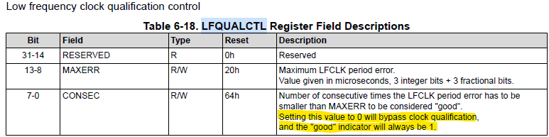
It acts as if LFQUALCTL.CONSEC is set to 0, but they have verified that it is not.

Summary Issue
For reasons we don't understand, LFCLKGOOD seems to immediately get set regardless of the actual crystal state.
We have already verified that the internal LF oscillator is disabled and that LFCLKGOOD is initially 0.
Please let us know of any questions or clarifications needed.

Thanks,
Luke
  • Hi Luke, 

    Thank you for reaching out. We will need to get some support from the design team. Please bear with us. 

    I believe at one point we will need to know the content of "MAXERR" - nice if you could get this information :) 

    Best regards, 

  • Hello,

    I work for Luke's customer.  MAXERR and CONSEC are not being adjusted and are equal to their reset values, 20h and 64h respectively.

    I hope this helps,

    Rick

  • Hi Rick, 

    Thank you for sharing I am awaiting some inputs from the team. I

    Please bear with me. 

    Best regards, 

  • Hi, 

    Thank you for your patience. 

    First of all, I would like to make you aware that the LF good indicator in CC2340R2 is not a fully reliable indicator of the clocks being stable. This has been found under validation and the software shipped within the SDK implements the required workarounds.
    The following is recommended: Before switching to the clock, the SW needs to ensure that the LF clock is stable. To make sure this is the case, it is recommended to wait for 1s after switching on LFXT, and 100ms after switching on LFOSC before switching them to the main clock

    However this does not explain the behavior of the GOOD signal in your case, this will have to be considered when developing your software.

    To go back to the LF good signal not working at all - This behavior has not been observed so far. For sanity, I believe we should check on the procedure you follow to switch on LFXT. 
    Could you please share such procedure with us so we can review? 

    Best regards, 

  • Hi,

    Thanks, this helps.  It looks like from your reply that we cannot do what we were wanting to do.  Just to be clear I will restate that what we want to do.  We are trying to measure the crystal start up time of the external low frequency crystal.  We are using DIO20 as a port pin to measure this amount of time.  When we allow the crystal to start, we raise DIO20 and when the LFCLKGOOD signal is true we will lower DIO20.  Also we are exporting the LF clock signal out on DIO12.  This allows us to capture the scope plot above that show the LFCLKGOOD signal is occurring before the crystal actually starts.   Below is source code that will allow you to see this occur.  We just call it in main() after board_init() runs before app_main() and the scheduler starts.

    // Turn off HFXT and LFXT crystals
    HWREG(CKMD_BASE + CKMD_O_HFXTCTL) &= ~CKMD_HFXTCTL_EN_M;
    HWREG(CKMD_BASE + CKMD_O_LFXTCTL) &= ~CKMD_LFXTCTL_EN;

    /* Enable LFCLKGOOD Note the LFCLKGOOD block is not directly connected to LFXT.
    * See the LFCLK link, 3 steps below */
    HWREG(CKMD_BASE + CKMD_O_IMSET) = CKMD_IMASK_LFCLKGOOD;

    // Clear the RIS LFCLKGOOD flag by setting the ICLR register for the GOOD bit.
    HWREG(CKMD_BASE + CKMD_O_ICLR) |= CKMD_MIS_HFXTGOOD_M + CKMD_MIS_LFCLKGOOD_M;

    // route LFXT to 32K bus
    /* Set LFCLK */
    HWREG(CKMD_BASE + CKMD_O_LFCLKSEL) = CKMD_LFCLKSEL_MAIN_LFXT;

    // route 32K bus to Clock out pin
    Crystal_OSC_Output();

    // turn on LFXT
    HWREG(CKMD_BASE + CKMD_O_LFXTCTL) = CKMD_LFXTCTL_EN;

    // DIO20 High [ start of osc time ]
    HWREG(GPIO_BASE + GPIO_O_DOUTSET31_0) = 1 << MY_STARTUP_TIME_OUTPUT;

    while(1)
    {
    small_delay(); // delay a hundred or 2 microseconds
    // If LFXT is Enabled, Test for the LFXT GOOD Flag
    if (HWREG(CKMD_BASE + CKMD_O_RIS) & CKMD_MIS_LFCLKGOOD_M)
    {
    // iF the Good Flag is Set, Clear DIO20
    HWREG(GPIO_BASE + GPIO_O_DOUTCLR31_0) = 1 << MY_STARTUP_TIME_OUTPUT;
    break; //Break from Loop
    }
    }

    // Done

    void Crystal_OSC_Output(void)
    {
    uint8_t clockSrc = 0x0F; //for LF crystal clock

    // drive output low first
    GPIO_setConfig(12, GPIO_CFG_OUTPUT | GPIO_CFG_OUT_LOW);

    // Configure the IOC.IOC12.PORTCFG MMR to select DTB
    HWREG(IOC_BASE + IOC_O_IOC12) &= ~IOC_IOC12_PORTCFG_M;
    HWREG(IOC_BASE + IOC_O_IOC12) |= IOC_IOC12_PORTCFG_DTB;

    // Make sure the DTB mux selects in IOC (and if required in
    // source clock IP) are reset that zero is driven on DTB0.
    // ULLSEL mux select (select CKMD)
    HWREG(IOC_BASE + IOC_O_DTBCFG) &= ~IOC_DTBCFG_ULLSEL_M;
    HWREG(IOC_BASE + IOC_O_DTBCFG) |= 0x1 << IOC_DTBCFG_ULLSEL_S; // 0x1 to route CKMD to DTB0

    // Map DTB[2:0] to DTB[15:13]
    HWREG(IOC_BASE + IOC_O_DTBCFG) &= ~IOC_DTBCFG_PADSEL_M;
    HWREG(IOC_BASE + IOC_O_DTBCFG) |= IOC_DTBCFG_PADSEL_DTB2TO0;

    // Enable IOC.DTBOE.EN0
    HWREG(IOC_BASE + IOC_O_DTBOE) &= ~IOC_DTBOE_EN0_M;
    HWREG(IOC_BASE + IOC_O_DTBOE) |= IOC_DTBOE_EN0_ENABLE;

    // select which clock (CKMD) to output on DTB0 (DTB[0])
    HWREG(CKMD_BASE + CKMD_O_DTBCTL) &= ~CKMD_DTBCTL_CLKSEL_M;
    HWREG(CKMD_BASE + CKMD_O_DTBCTL) |= (clockSrc) << CKMD_DTBCTL_CLKSEL_S;

    // enable DTB output
    HWREG(CKMD_BASE + CKMD_O_DTBCTL) &= ~CKMD_DTBCTL_EN_M;
    HWREG(CKMD_BASE + CKMD_O_DTBCTL) |= CKMD_DTBCTL_EN;
    }

  • Hi Rick,

    Hope you are doing well! I will be supporting you on resolving this as soon as possible. I have reached out to our R&D team with the latest information you have shared and I will let you know once I have heard back.

    Best Regards,

    Jan

  • Hi Rick,

    Could you provide the source code of the small_delay()? The R&D team would like to see the exact procedure done by that function to achieve the delay.

    Best Regards,

    Jan

  • Hi Jan,

    That part of the code was just pseudo code.  Any kind of delay or no delay at all will probably work. So no I cannot provided code for that small delay.

    The actual code just loops through a bigger part of the code and checks a port pin to ensure that we are still testing the low frequency crystal and then comes back.  I was just guessing that the time to get back to test the pin would be a 100 or so microseconds.

    Thanks,

    Rick

  • Hi Rick,

    Understood. I will let the R&D team know. Thank you for the quick response on this.

    Best Regards,

    Jan

  • Hi Rick,

    Just got word back from R&D and they suggest the following:

    1. Disable all LF Oscillators (LFOSC and LFXT)   (HWREG(CKMD_BASE + CKMD_O_LFXTCTL) = 0x0, HWREG(CKMD_BASE + CKMD_O_LFOSCCTL) = 0x0)
    2. Wait on LFCLK.STAT.LFGOOD to go low (while(HWREG(CKMD_BASE + CKMD_O_LFCLKSTAT)&CKMD_LFCLKSTAT_GOOD) )
    3. Clear LFGOOD RIS with ICLR  (HWREG(CKMD_BASE + CKMD_O_ICLR) = CKMD_ICLR_LFCLKGOOD_M))
    4. Switch to LFXT (LFCLK SEL)
    5. Enable LFXT
    6. Set DIO HIGH
    7. Wait for RIS_LFCLKGOOD == 1
    8. Set DIO LOW
    9. Measure Toggle width for Startup time

    Best Regards,

    Jan

  • Thanks Jan,

    I can't wait to try this!  I will post if it works for us.

    Thanks,

    Rick

  • Hi Rick,

    Sounds good! Let me us know how the test results look!

    Best Regards,

    Jan

  • Jan,

    This did work for us.  Thank you.

    Rick

  • Hi Rick,

    Glad to hear! I will mark this thread as closed for now. If you have any further questions on this topic feel free to reply to this comment or create a new thread if a new topic comes up.

    Best Regards,

    Jan