This thread has been locked.

If you have a related question, please click the "Ask a related question" button in the top right corner. The newly created question will be automatically linked to this question.

CCS/SIMPLELINK-CC2640R2-SDK: v2.40: RTOS I2C compared to Sensor Controller I2C.

Part Number: SIMPLELINK-CC2640R2-SDK
Other Parts Discussed in Thread: CC2640R2F, CC1350

Tool/software: Code Composer Studio

Hi,

We interface I2C LSM303AGR Accelerometer + Magnetometer Sensor to CC2640R2F. We used Sensor Controller I2C to communicate with it and it works 100%. When the LSM303AGR is flat on the ground the accelerometer reading is around X = 0 mg, Y = 0 mg, Z = 1000 mg. 20/20 samples from Sensor Controller is good.

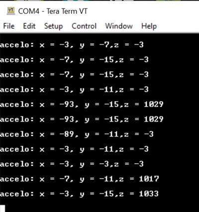
We decide to use RTOS to communicate with I2C LSM303AGR. So I port the Sensor Controller code to RTOS and the output is not consistent, see below. The accelerometer Z should be always be around 1000 mg. I would like to know if there is any issue with RTOS I2C at SDK 2.40. I have read in this forum that there is a problem with I2C at CC1350 SDK but I am not sure if that affects also CC2640R2f RTOS I2C.

-kel

  • Please start by using the newest SDK (3.20) and see if you get the same problems there.

    BR

    Siri

  • Hi,

    I tried with SDK 3.20 and same results, the issue is not related to I2C. I made some improvements to the code and now the output is slighter better but not okay see, below.

    acc mg: x = 3903, y = 3978,z = 1025

    acc mg: x = 3907, y = 3974,z = 1021

    acc mg: x = 3907, y = 3978,z = 1017

    acc mg: x = 3907, y = 3974,z = 1029

    The code to get the acc mg is this below. Below are just the important parts for the issue. 1 bit is equivalent to 3.9 mg.

    typedef struct lsm303AccelData_s
    {
    int16_t x;
    int16_t y;
    int16_t z;
    } lsm303AccelData;

    uint8_t acc_buffer[6];

    accelData.x = ((((int16_t)acc_buffer[1] << 8) | (int16_t)acc_buffer[0]) >> 6) * 3.9;
    accelData.y = ((((int16_t)acc_buffer[3] << 8) | (int16_t)acc_buffer[2]) >> 6) * 3.9;
    accelData.z = ((((int16_t)acc_buffer[5] << 8) | (int16_t)acc_buffer[4]) >> 6) * 3.9;

    Before converting the value to mg is this below.

    accelData.x = ((((int16_t)acc_buffer[1] << 8) | (int16_t)acc_buffer[0]) >> 6);
    accelData.y = ((((int16_t)acc_buffer[3] << 8) | (int16_t)acc_buffer[2]) >> 6);
    accelData.z = ((((int16_t)acc_buffer[5] << 8) | (int16_t)acc_buffer[4]) >> 6);

    The issue now using RTOS C, is bit shifting right a signed short or int16_t. example given the below acc_buffer[] values.

    acc_buffer[0] = 128,  //LSM303AGR_OUT_X_L_A

    acc_buffer[1] = 249; //LSM303AGR_OUT_X_H_A

    acc_buffer[2] = 192; //LSM303AGR_OUT_Y_L_A

    acc_buffer[3] = 254; // LSM303AGR_OUT_Y_H_A

    acc_buffer[4] = 128; //LSM303AGR_OUT_Z_L_A

    acc_buffer[5] = 65; //LSM303AGR_OUT_Z_H_A

    So, before bit shifting right 6.

    accelData.x = -1664 = 1111 1001 1000 0000

    accelData.y = -384 = ‭  1111 1110 1000 0000‬

    accelData.z = 16768 = 0100 0001 1000 0000

    After bit shifting right 6. As you can see when you bit shift right a signed short or int16_t 1 is also bit shifted. I forgot the explanation for that. But that is correct. So for Sensor Controller this happens. Multiply the values by 3.9 to convert it to mg. This is correct.

    accelData.x = -26 = ‭1111 1111 1110 0110‬ 

    accelData.y = -6 =  ‭1111 1111 1111 1010‬

    accelData.z = 262 = ‭0000 0001 0000 0110‬

    However if I use RTOS C to bit shift right a signed short or int16_t the issue appears. The bit shifting right operation is same to a positive value. This is wrong.

    accelData.x = 998 = 0000 0011 1110 0110 

    accelData.y = 1018 = 0000 0011 1111 1010

    accelData.z = 262 = ‭0000 0001 0000 0110‬

    So, why using RTOS C there is problem bit shifting right a signed short or int16_t? Is there any way I can improve my code to get the correct results?

    -kel

  • I am not able to see that the ther are any difference in how bit shifting of an int16 using tirtos comapared to not using tirtos.

    Please take one of the examples from the SDK that is available for both TI-RTOS and nortos, and make a small example showing how shifting is done differently.

    I took at look at the data sheet for the lsm303 and it states that the data are two’s complement left-justified, so why do you want to shift the data to the right?

    If there is differences in how bits are shiftet, we will certainly look into that, but it might be usefull so check with

    STMicroelectronics to make sure teh conversion is done correctly. The best is if they can provide some examples on 8 bits values read from

    OUT_X_L_A), OUT_X_H_A etx, and then have them show how this should be interpretd/converted.

    Siri

  • Hi Siri,

    Thanks for your time. Here is the code from ST Micro Code Library. The bit shifting right 6 is when the LSM303 range is set to +2g/-2g, 10 bit normal mode

    /* Read output registers from LSM303AGR_ACC_GYRO_OUTX_L_XL to LSM303AGR_ACC_GYRO_OUTZ_H_XL. */
    if (!LSM303AGR_ACC_Get_Raw_Acceleration( (void *)this, ( uint8_t* )regValue ))
    {
    return LSM303AGR_ACC_STATUS_ERROR;
    }

    /* Format the data. */
    pData[0] = ( ( ( ( ( int16_t )regValue[1] ) << 8 ) + ( int16_t )regValue[0] ) >> shift );
    pData[1] = ( ( ( ( ( int16_t )regValue[3] ) << 8 ) + ( int16_t )regValue[2] ) >> shift );
    pData[2] = ( ( ( ( ( int16_t )regValue[5] ) << 8 ) + ( int16_t )regValue[4] ) >> shift );

    So, I re-use the code at Sensor Controller, and it works 100%. It's been working more than 8 months and all data we get is good. We are happy with that.

    output.accX = (((output.accbuffer[1] << 8) | output.accbuffer[0]) >> 6);

    output.accY = (((output.accbuffer[3] << 8) | output.accbuffer[2]) >> 6);

    output.accZ = (((output.accbuffer[5] << 8) | output.accbuffer[4]) >> 6);

    Since, Sensor Controller don't have enough space for our next improvement. We decide to move the code to Main Application RTOS. Here is the code as I have shared earlier, which has problems.

    accelData.x = ((((int16_t)acc_buffer[1] << 8) | (int16_t)acc_buffer[0]) >> 6);
    accelData.y = ((((int16_t)acc_buffer[3] << 8) | (int16_t)acc_buffer[2]) >> 6);
    accelData.z = ((((int16_t)acc_buffer[5] << 8) | (int16_t)acc_buffer[4]) >> 6);

    But, last night I was able to get the correct results by separating the operations. Which is good to me. But then I have to explain this to other people. Why using ST Micro MCU there is no problem performing these operations in 1 code line. But then using TI CC2640R2F using ARM Cortex-M4 there is a problem performing these operation in 1 code line. Anyway, I will mark this post as answered. Maybe you can discuss this internally with TI Compiler team.

    accelData.x = (((int16_t)acc_buffer[1] << 8) | (int16_t)acc_buffer[0]);
    accelData.y = (((int16_t)acc_buffer[3] << 8) | (int16_t)acc_buffer[2]);
    accelData.z = (((int16_t)acc_buffer[5] << 8) | (int16_t)acc_buffer[4]);

    accelData.x >>= 6;
    accelData.y >>= 6;
    accelData.z >>= 6;

    accelData.x *= 3.9;
    accelData.y *= 3.9;
    accelData.z *= 3.9;

    -kel

  • I talked to the guy who made the sensor controller and he said that the differences were likely due to different compilers for the sensor controller and the M4, and could also be related to the sensor controller having 16 bits registers while the M4 has 32 bits.

    Also, see:

    BR

    Siri

  • Thanks.That makes sense.