This thread has been locked.

If you have a related question, please click the "Ask a related question" button in the top right corner. The newly created question will be automatically linked to this question.

TRF7960 Cannot read back

Other Parts Discussed in Thread: LM3S6950, TRF7960

Hi all,

I am currently working with TRF7960 and LM3S6950

I have a problem of writing and reading back a register after Power on.

In the firwmare, after power on and setting up clock and peripherals (GPIO, SSI, etc), it writes the address of 0x0B and then output clock pulses to read its value (the deafult value of 0x0B register is 0x87)

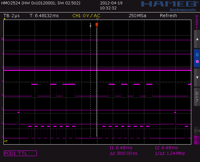
I check the waveform of SPI bus and it is correct (TCK, SS, MOSI) but there is no response from MISO pin (MISO should return 0x87)

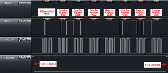
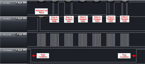
The picture file is the waveform that I capture.

,

      Line7 = TCk, Line6 = SS, Line5 = MISO, Line4 = MOSI, Line3 = EN

  Because it reads 0x0B => it will write 0x4B to TRF7960 and then write a dummy data to pulse clocks and read back value from TRF7960 (but Line5 is alway 0s in my case !!!)

  It can be checked that the polarity of TCK has been changed to falling edge capture for reading.

Note: I use the reference schematic described on page 10 of the datasheet of TRF7960 but I use 3.3V for both the MCU and TRF7960's VIN pin.

     I also check output voltage of internal regulators of TRF7960, they are correct (VDD_A=2.7V, VDD_RF=3.2V,VDD_PA=3.2V,VDD_X=2.6V)

Could anyone help me what should I check or whether I need to configure TRF7960 before reading or writing its registers ?

Thanks

Huy

  • Hi all,

    I want to add more info about my circuit:

    - The MCU does not use SYS_CLK from TRF7960, it has a crystal of 8MHz

    - The SPI frequency is 1MHz

    I use SSI1 to interface with TRF7960

    The code to read register 0x0B of TRF7960:

            CLEAR_TRF_CS_n;
            SSI1_DR_R = 0x4B;                                       // write address to read reg 0x0B
            while(SSI1_SR_R & SSI_SR_BSY);
            temp = SSI1_DR_R;
             SSI1_CR1_R &= ~SSI_CR1_SSE;              // disable SSI module to change clock polarity for reading
             SSI1_CR0_R &= 0xFFFFFF3F;                     // clear SPH-SPO bits of CR0 register
             SSI1_CR0_R |= 0x00000080;                      // change SPH-SPO to 10
             SSI1_CR1_R |= SSI_CR1_SSE;                  // enable SSI module
             SSI1_DR_R = 0x55;
             while(SSI1_SR_R & SSI_SR_BSY);
             reg[0]= SSI1_DR_R;                                       // store the read value
             SSI1_CR1_R &= ~SSI_CR1_SSE;             // disable SSI module to change back clock polarity
             SSI1_CR0_R &= 0xFFFFFF3F;                    // clear SPH-SPO bits of CR0 register
             SSI1_CR1_R |= SSI_CR1_SSE;                 // enable SSI module  
             SET_TRF_CS_n;

    Regards,

    Huy

  • Huy -

    After you raise the EN line, did you verify that your 13.56MHz crystal is running? also - you can check the Bandgap voltage which should be 1.6VDC.

    If you are using the LM3S line of Stellaris MCUs, then i would recommend that you go request the firmware project example we have available for the TRF7960 + LM3S9B96. This would be probably most helpful to you as an example for the SPI w/SS firmware steps, which in this case (with the TRF7960), as you know, do require a polarity change between writes on MOSI line and reads on the MISO line.

    http://www.ti.com/tool/sw-dk-lm3s9b96-em2-trf7960-14443a&DCMP=STELLARIS®ARM®CORTEX+Other&HQS=Other+OT+sw-dk-em2-7960r

    Also, below is example of writing register 0x09 and then the ISO Control Register.

    Then here we are showing a write continuous on registers 0x00 to 0x0B

    and continuous read


  • Hi Josh,

    Thank you very much for your support.

    I will request the firmware for my reference.

    I also checked BAND_GAP pin and  it was 1.6V  as you said => It means that the 13.56MHz is running correctly, doesn't it?

    So, TRF7960 does not need any set up in order to make it in operation, is it right ?

    => Just power up and then I can read/write its registers.

    If it is so, I have no idea how to solve the problem because the waveform is correct (TCK, SS, MOSI) and all pins of TRF7960 are probed and their values seem to be correct  but MISO has no signal only !!!! @_@

    Here are the values of all pins I probed by my VOM:

    Pin     Value                       Pin           Value                              Pin         Value                    Pin          Value

    1       2.67V                        9                 0V                                  17           0V                         25            0V         

    2       3.23V                       10                0V                                 18            3.2V                     26             1V

    3       3.2V                          11               1.6V                              19            3.2V                     27             1.3V

    4       3.2V                         12               0V                                 20             0V                       28             3.2V

    5       0V                             13              0V                                  21             0V                       29             0V

    6       0V                             14               0V                                 22             0V                       30             1.2V

    7       0V                             15               0V                                 23             0V                      31              1.2V

    8       1.6V                         16              2.6V                               24            1V                       32              2.6V

    I also test all pin contacts of TRF7960 to the board by:

       - Measuring Ohm between GND and the footpint pad of every pin  => each pad will have an amount of resistance to the ground if its pin is in contact

         => All pads except gnd pads are OK (no infinite OHM occurs)

      - Measuring Ohm between adjacent pads  => short circuit between adjacent pads can be detected

        => No 0 ohm occurs => no short between pads

     => I think that TRF7960 has good contact to the board

    Could you please suggest what should I do next to solve the problem ?

    Thanks,

    Huy

  • Hi Josh,

    I checked the output pulses at SYS_CLK after power on, it seems to be incorrect because its frequency is just 30kHz not 60kHz or high frequency clock

    According to the datasheet of TRF7960 on page 14, it says that when EN is hight, SYS_CLK will switch from 60kHz to 13.56MHz.

    But in my case, SYS_CLK is just about 30kHz while EN is high.

    Does it mean that the TRF7960 is malfunctioned ?


    Regards,

    Huy

  • I want to update that I also checked pin 32 of TRF7960 (OSC_OUT) and there is a 13.56MHz clock

    So I think the crystal is working.

    Regards,

    Huy