This thread has been locked.

If you have a related question, please click the "Ask a related question" button in the top right corner. The newly created question will be automatically linked to this question.

TRF7960 - Why is its SPI interface noisy?

Other Parts Discussed in Thread: TRF7960, LM3S6950

Dear all,

I am working with TRF7960 for ISO15693 cards.

Currently, I can read/write control registers of TRF7960 and read a tag.

But I have a difficult problem that it can only read a tag whenever I touch my finger to IRQ line ( and MOSI line) of TRF7960!!!!!

If I left it untouched, then it cannot read a tag ID, but it notifies a collision when a tag presents

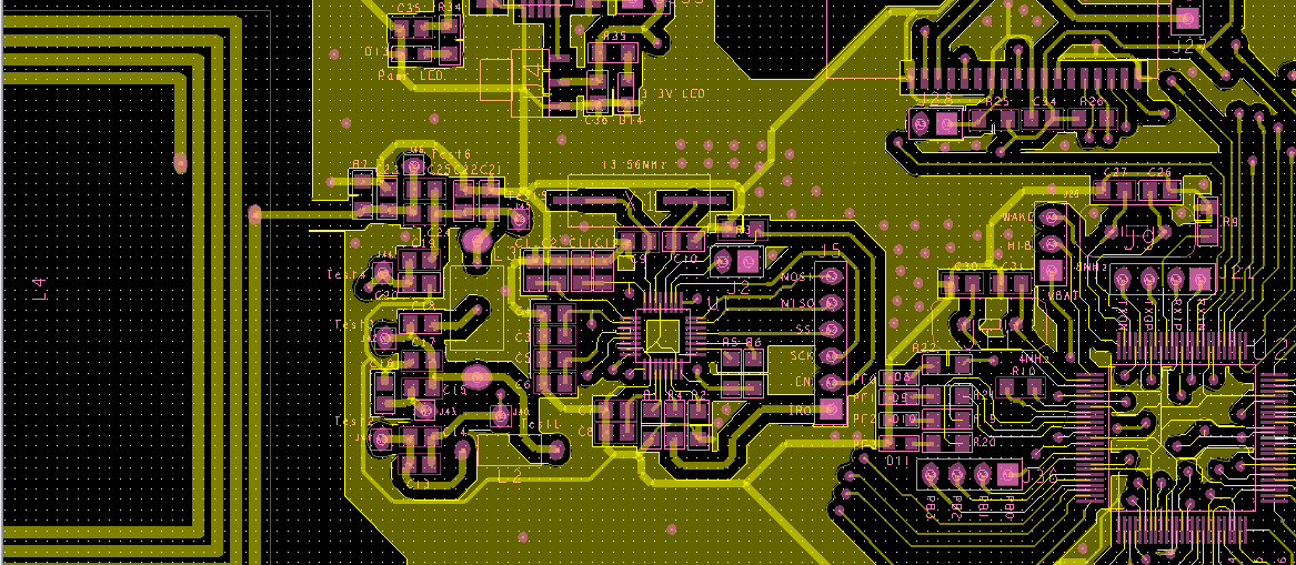
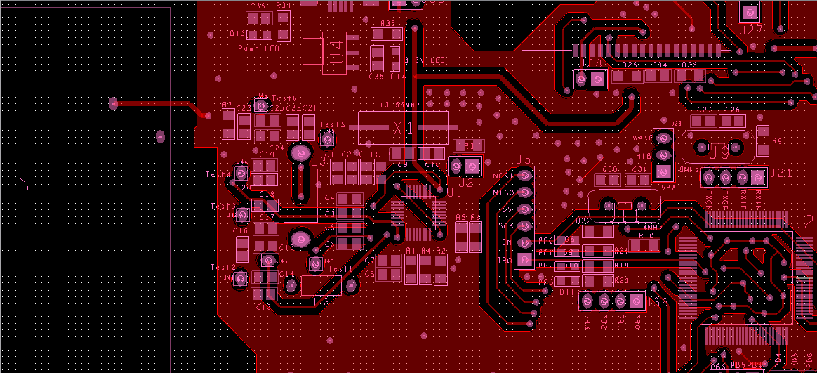
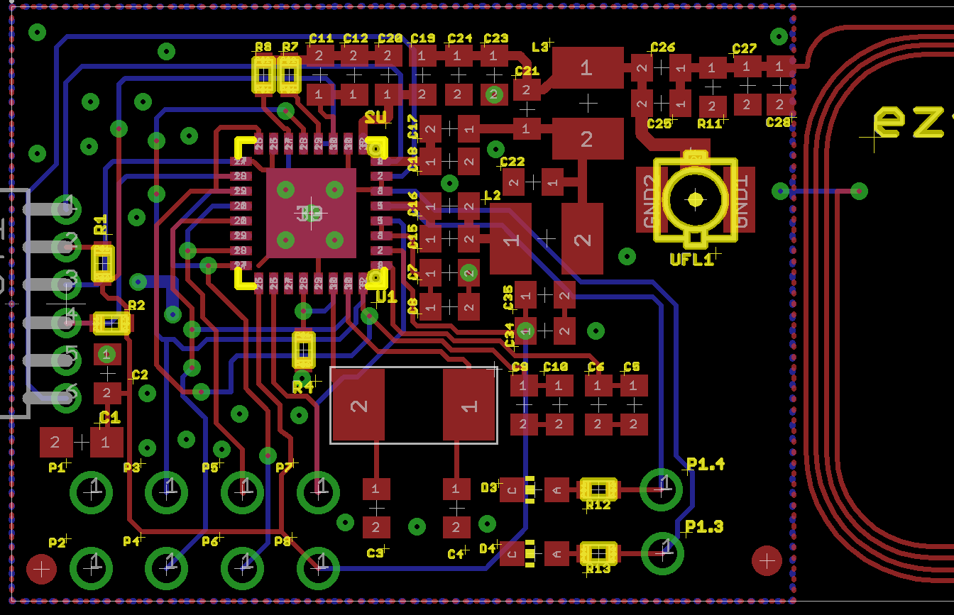
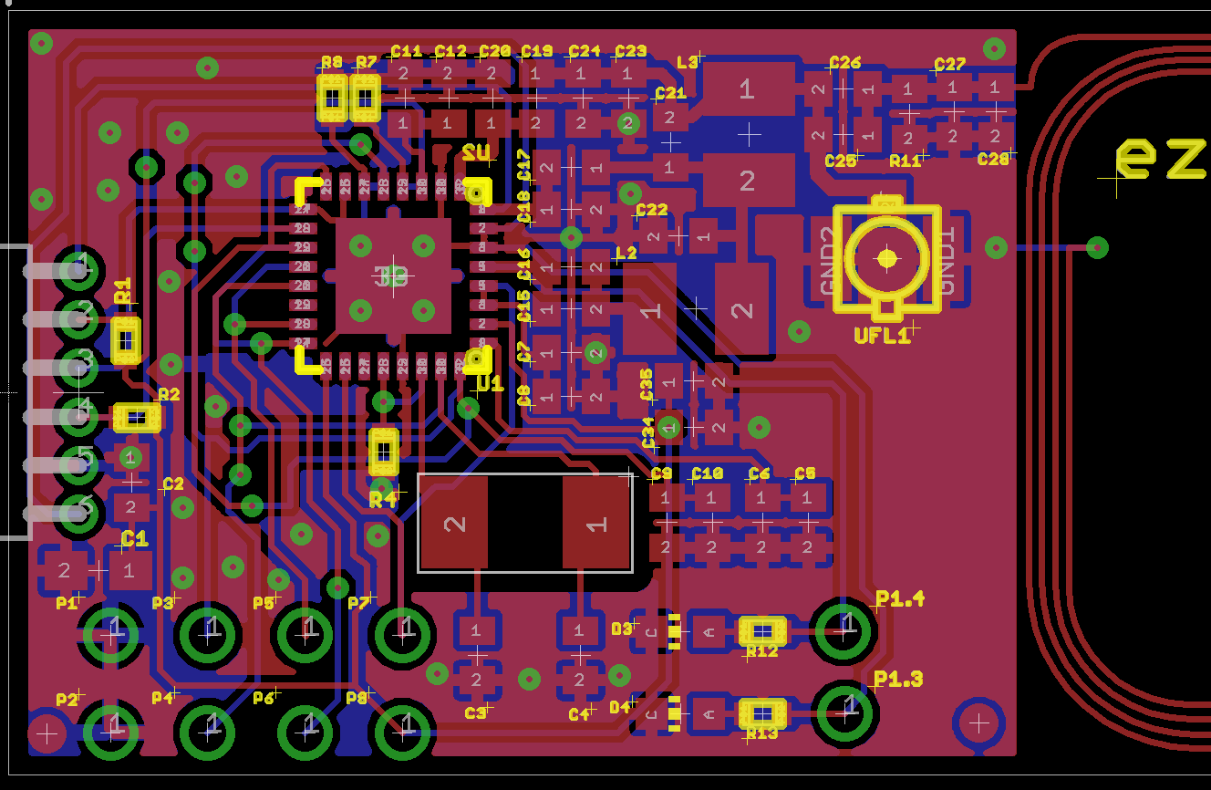
The board is professionally made by a company, not a home-made PCB.

What is the reason for my problem ? Is there any work around to fix that noisy problem ?

Thanks,

Huy

  • More than likely this is your layout or the layout combiend wiht the data clock frequency you are using - maybe it is close to the sub-carrier frequency (response from the ISO15693 tags, which is 424kHz or 484kHz)  - any chance to have a look at that?

  • Hi Josh,

    I show you the layout of my board:

    This is the TOP layer

    This is the BOTTOM layer

    As shown in the picture, the TRF7960 is at the left side, the MCU (LM3S6950) is at the lower right corner and another chip is at the upper right corner.

    The MCU use SSI1 module to interface with TRF7960 and SSI0 module to interface with the second chip.

    In the TOP layer, you can see the SPI interface lines between the MCU and TRF7960, they are far from TX_OUT, RX_IN pins.

    For your information, I can get TRF7960 detect a tag without touching my finger when I do not work with the second chip.

    But when I add functions to use SSI0 for that chip, TRF7960 could not work as before and I have to touch my finger => it works for sometimes !!!!

    Even if I disable the interrupt from SSI0 before it calls FindTags() function to make sure SSI0 does not affect the operation of detecting a tag, it still does not work !!!!

    (The second chip works correctly without any problem, only TRF7960 has problem)

    Then I comments all that functions that used for the second chip, TRF7960 works properly again.


    Regards,

    Huy

  • Huy -

    thanks for the pictures - i see alot of things which are of concern regarding the layout - first, you are not following the recommendations for the pad under the TRF IC itself. Then it looks like you have routed the TX part directly under the RX_IN1 chain. The rest of the layout looks pretty reasonable. If i could make a suggestion here - try replicating something closer to we have recommened for the layout of the RF section in our manuals, on our EVMs of what i am showing below. You can see that the TX chain DC block caps are very close to pin 5 and then the RX coming back in is well seperated.

    Without the fill on so you can see all the traces clearly