A related question is a question created from another question. When the related question is created, it will be automatically linked to the original question.
If you have a related question, please click the "Ask a related question" button in the top right corner. The newly created question will be automatically linked to this question.
Hi. I just want to increase RX sensitivity, as I’ve done previously with CC1020, where I inserted a SAW followed by LNA after the antenna switch. But CC112x reference design has a different arrangement for switching between TX and RX and it’s not clear to me where I can insert the SAW and LNA, both of which are 50 ohm in/out, without affecting circuit’s impedance.
Thank you Farrukh. I am familiar with the link you sent me, but taking that approach (which is for 169MHz application) would require component value changes for my 420-470MHz application, plus an antenna switch which I'm hoping to avoid with CC112x. Can I send you a schematic?
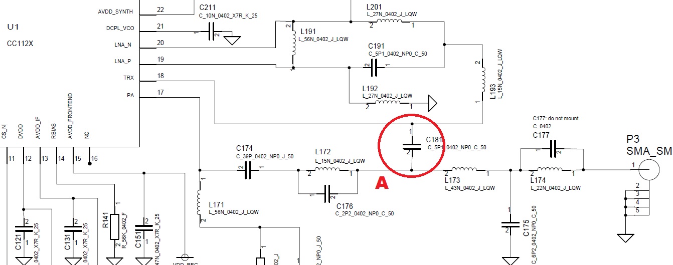
Thanks. The attached schematic is from TI's reference design (CC112xEM_420_470). I've highlighted capacitor C181 which taps off RX signals at point A. Ideally (unless you suggest otherwise) I'd like to remove C181 pin 2 from point A and instead connect my LNA/SAW circuit to point A. Then C181 would be connected to the output of my LNA/SAW circuit. However, for this scheme to work the impedance at point A needs to be 50 ohms as my LNA/SAW circuit has 50 ohms in/out. Any thoughts? Alternative solutions would involve an antenna switch, and component value changes, both of which I'd like to avoid if I can.
Ideally you could place the LNA where you have suggested and SAW instead of L173, C177, L174, and C175 to knock down harmonics. I believe the impedance at point A is 50ohm but i will verify this with simulation and get back to you.
I have attached the S11 file measured at point A by lifting L173 and setting the CC1120 in RX mode. Now this includes the effect of L172 and C176 portions of the network. This will help you with impedance calculations.
Also, for your particular application, you may have to tweak the balun to have impedance looking into the LNA/SAW to be 50ohm. Please see this AN068 for reference.


