This thread has been locked.

If you have a related question, please click the "Ask a related question" button in the top right corner. The newly created question will be automatically linked to this question.

TRF7970A: Value of capacitors on RX_IN1 pin

Part Number: TRF7970A
Other Parts Discussed in Thread: TRF7964A

Team,

I saw many TRF7970A hardware designs, and every RX_IN1 pin has 1200pF capacitors as below.

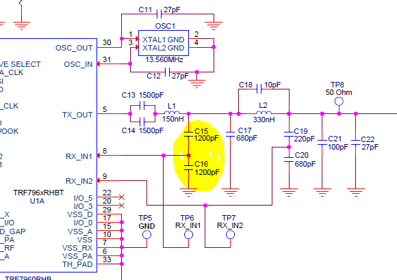
I have a question on these capacitors value. Can they be changed? if so, what is the recommended value for those? Is it mandatory to use 1200pF?

Best Regards,

Ted

  • Hello Ted,

    It is possible to change those, but changing them would affect the output of the TRF79xx Match Network we have designed. The network brings the 4 ohm output from the TRF79xx out to a 50 ohm point where an antenna can then be attached and tuned to 50 ohm. Getting the matching between the antenna and TRF79xx system is important to maximize RF performance.

    The matching network we provide is tried and tested over time, and at this point TI is not going to investigate the effects of changing any of the components along the network, so we don't have recommended values beyond the 1200pF used.

    The network was designed with LTSpice simulations, so a possible option would be to simulate changing components to achieve the same results (note, the start point would need to be a 4 ohm impedance source), but such efforts will not be supported from our end at this time.
  • I also have a project using TRF7954A, which will go into production soon.  In order to qualify the components being used on the RF paths, can you suggest a proper way of measuring the impedance at the 50-ohm point (towards the chip) using VNA?   I tried to make measurements with the chip powered off, but certainly it was not 50ohm, so I guess this was not a proper way.   Does the chip need to be powered up? what is the proper register settings needed to bring the chip to a proper state in which 50-ohm impedance could be measured?

    Please advice.

    Thanks.

    best regards,

    Paul

  • Sorry., a typo mistake, TRF7964A.
  • Hello Paul,

    Yes the chip needs to be powered on and emitting an RF field so bit 5 in register 0x00 (Chip Status Control) needs to be set.

    Make sure your measurement tool will be able to handle the peak to peak voltage swings (up to 10Vpp) for the RF field output.

    Here is a helpful slide deck of what to expect at various test points throughout the circuit:3125.0878.TRF79xxA_Test points_05_2013.pdf