Hello,
I am working on a keyfob for a vehicle remote keyless entry (RKE) system. I am using the RF430F5978 and am planning to design a pcb trace antenna for the 434MHz RF transmitter. I believe the best antenna option would be a small magnetic loop antenna since the keyfob will be handheld and the antenna could be susceptible to detuning. Since I have never designed an antenna or RF system before, I am hoping to get some feedback on the design so I can feel more confident that I'm on the right track before I build it.
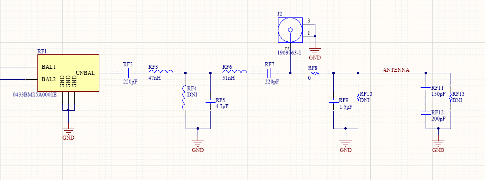
I followed the TI reference design for this family to get the basic RF output design for 434 Mhz (https://www.ti.com/lit/an/slaa462a/slaa462a.pdf), and then replaced the LP filter and balun with an integrated package to save some components and board space (https://www.johansontechnology.com/datasheets/0433BM15A0001E-AEC/0433BM15A0001E-AEC.pdf). Finally, I used a Microchip app note (http://ww1.microchip.com/downloads/en/appnotes/00868a.pdf) to estimate the values for the trace antenna and create a matching circuit for the loop antenna utilizing a tapped capacitor approach. This resulted in the following schematic:
I added a ufl connector (J2) with removable components on either side to make connecting test equipment easier. I also added resistors in parallel and in series with the loop (RF10 and RF13) in case they are needed to help with tuning.
For the pcb trace antenna, I followed the edge of the pcb outline to maximize the loop area. The antenna trace is 2.032mm wide and is 12.89cm long. The area inside the loop is 11.68cm^2. Based on these numbers, I calculated an estimated inductance of 92.10nH and a capacitance of 1.467pF.
1. Does this approach seem reasonable?
2. Is there anything I'm missing in this design?
3. Do the component values I've calculated make sense?
Thank you!


