This thread has been locked.

If you have a related question, please click the "Ask a related question" button in the top right corner. The newly created question will be automatically linked to this question.

TMS3705: Problem Initializing TMS3705 that respond Diag Byte but there are no Meaning of datata received from component

Part Number: TMS3705

Hi

My name is Cleber and my enterprise makes an automated feed that reads Tags FDX, and now, we are developing a board that must read HDX tags.
But I am having many problems to setup commands on TMS305.
At this moment,  all thing I did following information described on the datasheet makes me get no result.

After many days trying to get a tag Reading, I only get a Diag return, that sends a byte that has no Meaning for me because Datasheet doesn't have any reference about what does it byte received from TMS3705 means. Second, Using the sequence and timing suggested present inside datasheet, I get no tag reading from TMS3705 even seeing that data returned from a tag is on signal returned by antena coil. 

I found some image examples on the internet (even here in Ti e2e) but it does not specify detailed information (like time base) that is necessary to be implemented to ensure that Header will returns data from tag.

Who can help me to implement this?


  • Hello Cleber,

    I have not really got the point what the problem because you say that you can see the transponder is responding.

    I have some material for you that maybe contains information to help solve your problem:

    tms3705A_ed2.pdf

    TMS305_TP_Apr02_2002.pdf

    Let me now what exact info you will need to help you further.

    Best regards,

    Helfried

  • Hi Helfried!

    Thanks to sends me this material. Really helps a lot because it clears many doubts about how to drive this component. 

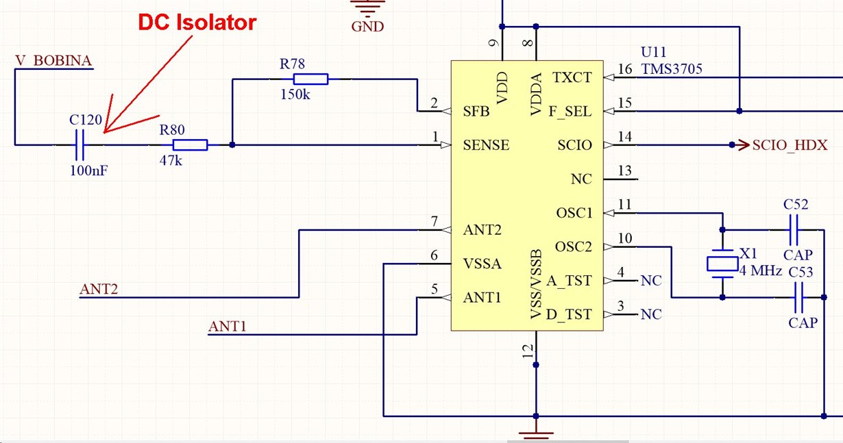
    Yesterday, I take a look in datasheet very carefully and detects many details that make antenna not responding, in this case, considering that I'm using external power drivers, it gives a DC signal of 8V at pin sense, what make tags not readable by drivers, since it has an internal 2,5V reference and because this, Pin SFB was saturated in 5V.

    My first solution applied was to use a Capacitor to couple AC signal without DC Levels from antenna to TMS3705, then immediately it starts to work and sends to microcontroller data read by the antenna. Is it correct (even considering that it is working)? I Must keep DC couple?

    But I have another point to be improved: must improve reading range (as always). For this, I must Know the maximum signal return from HDX tags should be processed by TMS3705. This manual talks about 5mv at pin sense, that has a virtual ground to 2.5V reference for analog signal, (maybe dB was better unit) but I have no idea about what level is better and what is bad and how to calculate appropriate resistors and gain. Your manual sent today talks about gain G=5 but calculates a gain of 3,19, I don't understand why this? Can you explain it?

    Finally, due to our application, I must use external 134.2kh clock signal instead 132,4kh provided by TMS. Will TMS3705 works? I Will keep pins unconnected, to not short-circuit the output driver, but I'm fear that TMS3705 will understand this as a failure. 

    Thanks for pay attention, and if necessary, I can send images to help to understand this. 

    Cleber Magalhães Gonçalves

  • Hello Cleber,

    this is good news that you now can receive your transponder data.

    As far as I understand you will not use the transmitter part of the TMS3705 and you generate you own transmit signal.

    This should be no problem. Because the fault detection for the antenna is part of the RX stage and you have now a cap as DC isolation included, the diag byte will show an antenna problem. The functionality should ne be affected.

    Regarding the R1/R2 values, my understanding is that with the 47k/150k you will have G=3.19, but the max value for G should be 5.

    In the datasheet a voltage of 5mVpp for the minimum input voltage for the bandpass is stated (which corresponds to the SFB pin). This will mean with a gain of 5 for the input amplifier you should have a minimum input voltage of 1mVpp.

    Best regards,

    Helfried


  • Hi again!

    About Mode Control Register, considering the first time device comes from power-up, after I programmer it one time, how to know that it's correct programmed? And It is necessary to reprogram this registry every read cycle or since it's programmed, I only need to run read process? 

    Best regards,

    Cleber Magalhães

  • Hello Cleber,

    because the MCR is a read only register you can not read back its content.

    It depends on what transponder you want to read. If you only want read a RO transponder the MCR does not need to be programmed.

    For all other cases the MRC needs to be programmed again. Programming of the MCR takes only around 1ms which is negligible if looking at the time for the complete read cycle. So I would recommend programming it at every cycle.

    Best regards,

    Helfried

  • There is a new challenger:

    Everything seems to be working "fine", I got 140Vpp in an antenna coil that has 136uH and it makes an output voltage (When output drivers are switched off) about 200mVpp (when fully couplet to antenna coil) and 50Vpp when tag is about 5cm from antenna coil wires. 

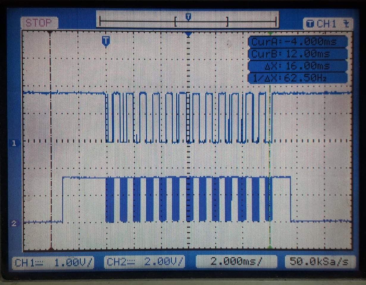
    I only get a correct tag read when it is fully coupled, as it can be seen on the image below:


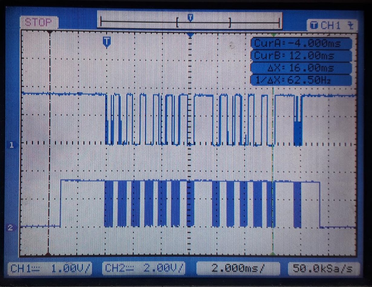
    In all other cases, the tag reading becomes this:

    With lacunes around the signals of the reading process, as it can be seen 8° and 14° bytes read by the program. 

    Even with a tag in a distance about 30cm from center of the antenna coil, it reads some bytes, but the numbers of lacunas increases.
    What may be the solution? To increase the gain of analog signals, or to reduce noise applying filters, or both.

    What do you recommend at this point?

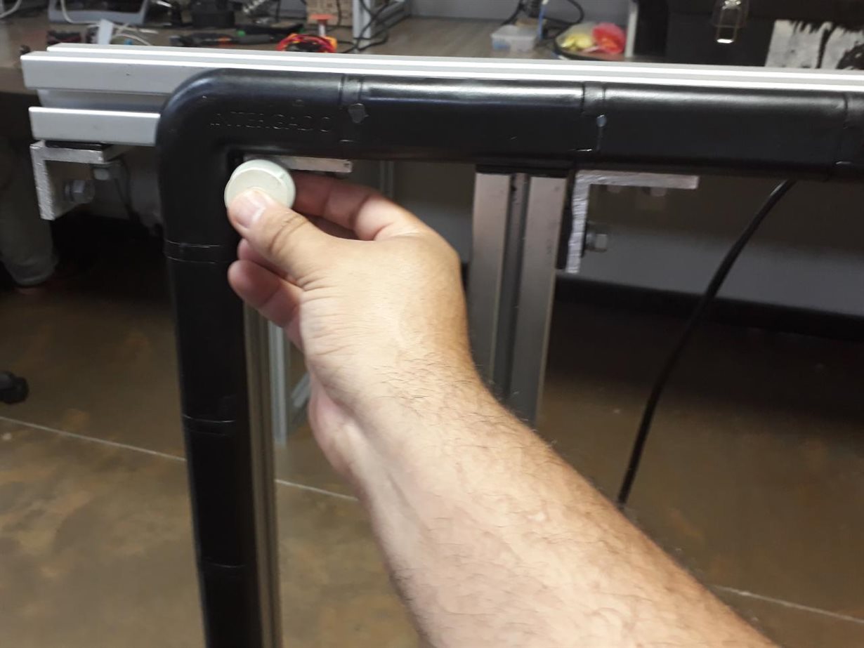
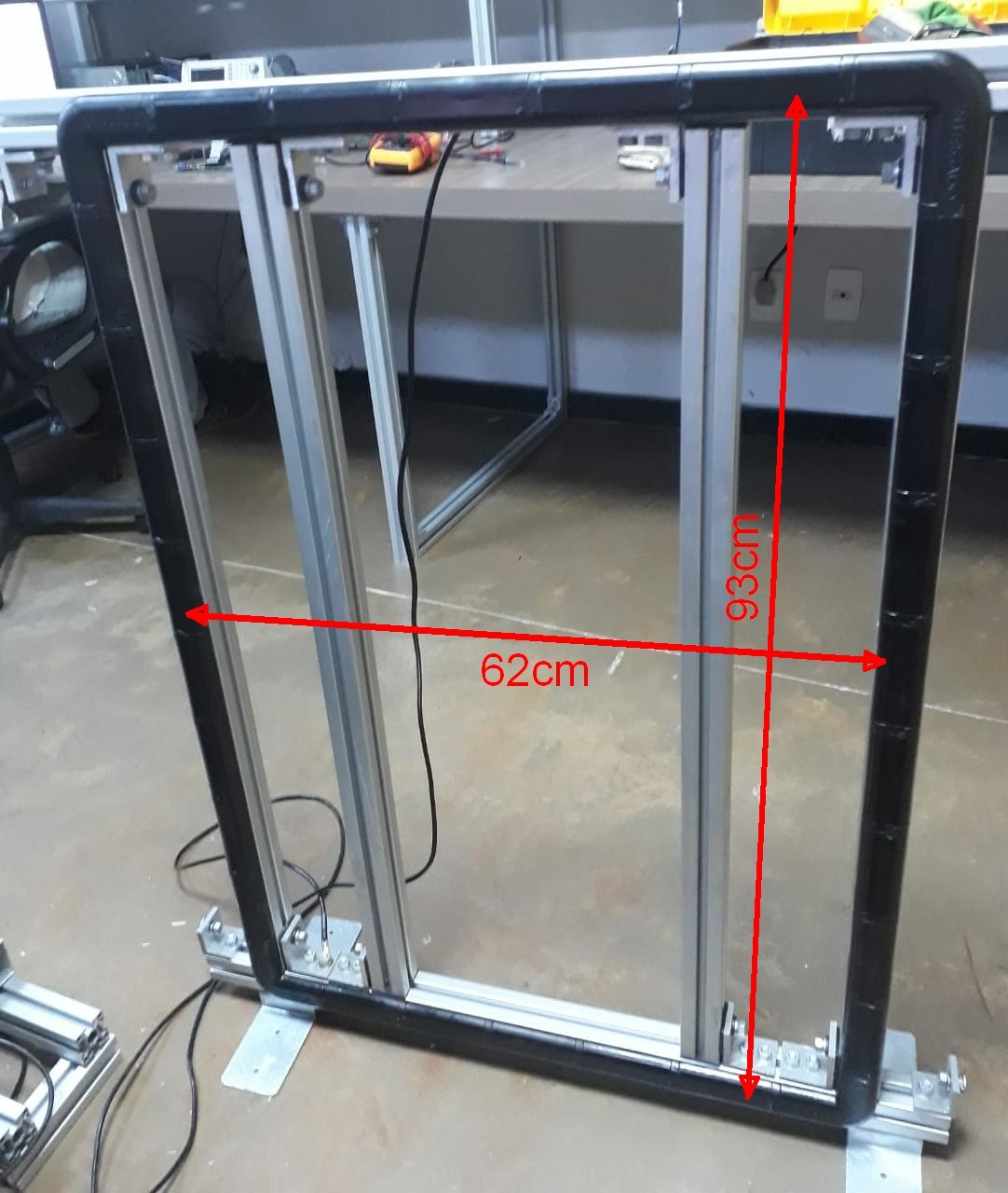
    Below pictures of antenna reading tag

    This Antenna has his base and his top connected to the ground, and there are isolators to block short circuit in metal support, and the cable is grounded from the board. 
    any help will be appreciated. 

    Best Regards,

    Cleber Magalhães Gonçalves

  • P.S. New detail.

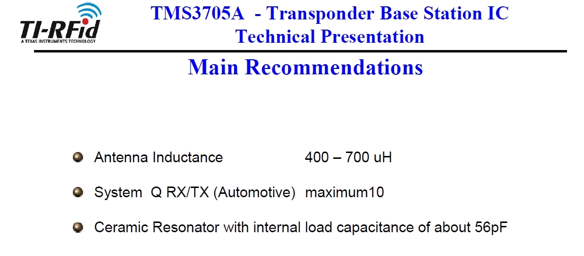
    As I read on the document [TMS305_TP_Apr02_2002.pdf] sent last time, at Page 28 I read that inductance must be between 400uH and 700uH and a maximum Q Factor of 10. We had already built an antenna that has an inductance of 135uH and Q Factor above 28. that is ideal for HDX reading.
    Is it not possible to use the same kind of antenna to read HDX and FDX Tags? We use discrete amplitude detector. 


  • Hello Cleber,

    thanks for the detailed description. I want to discuss that with college that is more experienced with this sort of problems but could not reach him so far.

    I will try to come back to you by end of the week.

    Best regards,

    Helfried   

  • Hi, Cleber again!

    Since my project must be done and understanding the process that HDX tags return data, I tried to make a circuit that to the same thing that TMS3705 Does.
    Firstly I made a circuit that amplifies signals from antenna coil to levels that after transformed to a square wave, it can be read by a microcontroller. Then, I would try to make a program to detect the frequencies of 129 and 134,2Khz from the tag, that it Would convert to 0 an 1.
    But when I saw a signal amplified by my circuit, I see that is better and great than signals applied directly to TMS via R1 and R2 (in my circuit, R80, and R78).

    I couple this signal using a capacitor and whola! It works! (not better than I Expect, but much Better than directly coupled signals from our big antenna coil to TMS3705) 
    At that point, the question is: What are the ideal returned signals in terms of levels? What level of signals will make TMS3705 efficient to read tags? Is important that 134,2khz signals (zero bits) from tag have the same level (in volts) of 129Khz signals (one's bits)?

    Any  Example Will be appreciated. 

    Best Resgards

    Cleber Magalhães

  • Hello Cleber,

    just had a discussion with a college about your circuit.

    A few thoughts about the TMS3705:

    - TMS3705 is designed for immobilizer reader with a communication distance of a few centimeters, which means it was not designed for high output power or high sensitivity.

    - TMS3705 can be used for long communication reader design, but it requires external transmitter and external pre-amplifier for receiver.


    - For the resonance circuit would be best to have High Q-factor for transmission and Low Q-factor for receive with bandpass filter


    I think you are doing well with your solution of an external amplifier for the receiver. As I wrote, the minimum input voltage for the TMS3705 should be 1mVpp. For the transmitter you already use your own high power stage.


    A problem can be the high Q factor of your resonance circuit which you mentioned has Q=28. This should be lower for the receiving of the two FSK frequencies to get equal levels for both frequencies.


    I found an old application note for a different reader IC which explains systems with different Q values.


    RF6AN20.pdf

    Maybe you can pick some useful information out of it.


    Best regards,

    Helfried