This thread has been locked.

If you have a related question, please click the "Ask a related question" button in the top right corner. The newly created question will be automatically linked to this question.

CC85XXDK-HEADSET-RD: wireless headset troubleshooting

Part Number: CC85XXDK-HEADSET-RD
Other Parts Discussed in Thread: CC8531, CC2590, CC2591

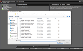
I took the reference design, and had some PCBs made.  I got 3 working to the point that they took the purepath programming.  Set up one as slave, one as master.

Press the power on button, and the red LED blinks about 1/sec.  Press the button again, and it blinks 2 times, then about a second, 2 times....  etc.

did this on both M & S they both do the double blink for about 10 sec, then go back to the 1/sec.

No audio send / receive.

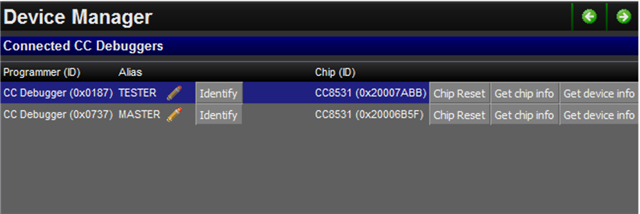
I tried swapping the 3 units around, S vs M, etc.

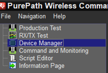
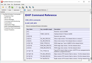
What / how do I check to find out what's not happening?

  • David,

    In the PPW Commander tool there are a series of production tests and RX/TX tests. I would recommend starting with these tests to see if you can establish a link. Additionally, you can use the "Command and Monitoring" tool in PPW Commander to execute EHIF commands which allow you to see network information, device information, etc.

    You can find help for these tools in the PPW Commander "Help" menu.

    Regards,

    Daniel 

  • Ok, I downloaded & run the PPW Commander.  [I only had the configurator, didn't even know of this commander]   It needs 2 boards, that I have.  I have 1 connected with the CC Debugger, and one plugged into the USB.  This doesn't work...  When I click program tester, I get the error "tester not connected".  

    I'm missing something, but not sure what.  Do I need a second CC debugger?

    Thank you,

    Dave

  • David,

    Yes, some of these tests require 2x CC debuggers. Others (like the Simple RF Tests) only require 1. However, you can still use the PPW Commander "Command and Monitoring" tool to connect to 1 of the devices. To see all the available tests, click "Configure..."

    When you are trying to pair the devices it might be useful to use "Command and Monitoring" to see that states of the devices. You can view all available commands in the "EHIF Command Reference" section of the help documents.

    Are there any differences between your hardware and the reference design? Have you made sure all devices are running properly configured code and have the latest firmware?

    Regards,

    Daniel

  • Regarding the  EHIF  I found this - -  Before any operation on the EHIF can be done, it is necessary to select a CC debugger. This is done by the ID command. This command takes one argument; the USB ID or alias of the debugger (see Device Manager).   

    I have programmed 1 board as a master, one as a slave, but I can't find the CC debugger in the windows device manager to get the name to tell the ID command.  It seems that this has to happen before I can do anything else with EHIF.

    The design -  I printed the reference design schematic.  part by part, wire by wire, I crossed each off the print as I entered them into CADSTAR.   I kept the RF parts of the layout as close as possible to the original layout, since I know I don't know enough about RF PCB design to mess around with it.  Some other parts are routed / positioned differently.

    [the original supplied CADSTAR design files are set up so differently that they are unusable, and there was some kind of error regarding hole diameters that I could not fix, and no one at TI could fix.   I couldn't run correct gerbers from them, the board house couldn't use what I could get.   So I had to start from scratch and re enter and copy the entire thing.]

    Thank you,

    Dave

  • Dave,

    In the PPW Commander program, you should see something like the following when your CC Debugger is plugged into your PC in the Device Manager view

    The hex value is what you use to select the debugger to use EHIF commands.

    If you have specific questions about your hardware design, please post them in a new thread and I can assign one of our hardware experts to help. Otherwise you can request a design review here: https://www.ti.com/tool/SIMPLELINK-2-4GHZ-DESIGN-REVIEWS 

    Regards,

    Daniel

  • Ah, ok, I got it to take the ID.  As far as the EHIF commands,  I tried a few, don't know if I did them correctly, got no obvious results or error messages.

    The design review is probably a good idea, to be sure I got everything correct.


    Thank you,

    Dave

  • In the design review - they want stack up information...  What is this referring to?  I have the schematic, BOM, gerber files.  Never heard of stack up.

  • PCB stack up refers to the arrangement of layers of copper and insulators. For example, you might have 2 copper layers (top and bottom) and 1 insulating layer between them. Most PCB CAD tools will export this information.

    Regards,

    Daniel

  • Hi Daniel,
    I finally got a second CCdebugger.   I can see them both in the device manager.  Is there any tutorial / guide to  guide one through how to do anything with this system?   I really don't know where to start.

    Dave

  • David,

    You can view EHIF command help in the PPW Commander Help. 

    The Command and Monitoring Panel help menu will show you how to use the EHIF commands in PPW Commander

    Regards,

    Daniel

  • Yes, I found those.  Everything is written like I already know exactly what it all means, and how it works, and what to enter, and what to expect for results.  I can't figure out how to get anything much to happen, or what any of the very few responses I've gotten mean.  Most command attempts result in the entry line getting cleared, and no other indication of anything else.

    They only thing I think may have done something was ID(0220), which put 0x0090> at the left of the entry line area.

  • I went to the Device Manager item, got the ID (0x0220) for one of the CC debuggers.  Then go to the Command and Monitoring item.

    after doing the id (0220), which puts the 0x0090 to the left of the entry box.

    When I try this command - di_get_chip_info(0x00b0)    

    While typing, it shows possible commands above - if I miss a character, they disappear.
    As soon as I type the last ), the line of text disappears.  Hitting enter or the run button does nothing.

  • David,

    Sorry you are having issues. When you type ID, can you try using the hex value? 

    id(0x0229)

    You should see a command history on the left column, and the retuned values on the right. My guess is that using a decimal format is causing PPW Commander to send commands to an invalid USB Destination.

    Now that you have 2 CC Debuggers, you can also try the RX/TX or Production tests to try to establish communication between the devices.

    Regards,

    Daniel

  • OK, I thought I had typed the x....  But apparently not..  I did the ID(0x0220)  and, now I get the 0x0220 to the left.
    When I type the di_get_chip_info(0x00b0) line, It stays but it still just clears when I hit enter, nothing ever displays on the left or right big areas.

    So far, I've only been trying to get some kind of response.  I'll have to look at the RX/TX thing tomorrow...

    Dave

  • When I click the run all button, it adds a new "Test sequence duration:.... "  line.
    But what does this mean?  I don't see any indication that the test passed or failed?  

    The error came when I clicked the program tester button [I see this test doesn't need a tester]]

  • David,

    I'm not sure why the commands aren't working on the Command and Monitoring window for you. I haven't seen the behavior you are describing before. What version of Windows are you running?

    For the Product Test you are running (prod_test_pairing), you will see when you first select the .ppwptc file (using the "configure.." button) that it expects certain aliases for the DUTs.

    Most of the tests require aliases for the devices used in the test, and PPW commander should tell you what aliases to use. You can set the aliases in the Device Manager view.

    Once you have the aliases set and the devices connected, you can click "Run All" to execute the steps listed under "Test Name"

    I think the reason the test is ending so quickly/ not doing anything is because it is trying to run the listed tests on devices with matching aliases, and it doesn't find any.

    Regards,

    Daniel

  • So far, I have been trying to use the thing with what it opens with, which happens to be the pairing test.  I figured it had a simple test setup as default.

    Anyway -

    OK, When I went to the device manager to look for how to put the aliases, I found the Chip Reset Get chip Info Get device Info are actually buttons that can be clicked.  Clicking reset gets no response, but the other 2 buttons [x2] give me the error box.

    The CC debuggers have their green LED on, and the identify button blinks one of the LEDs, one for each, so that seems to work.


    The boards I have start flashing an LED when I hold down one of the buttons - unless I connect the CCdebugger.  They don't respond to the button when connected, and I also tried starting one, and then connecting the debugger, which stopped it.  I have the debugger connected to the header that goes right to the CC8531RHAT IC.

    I double checked the pins on the header vs the debugger, the names match up.

  • oh, windows 10 pro,  build 19043

  • David,

    This is definitely strange behavior. I'm starting to suspect there might be hardware issues. What is the status of your hardware review?

    Regards,

    Daniel

  • Hi Daniel,
    They are starting on it.   

    Thank you,

    Dave

  • I got some info from the design review...  One thing they found is that C211 and C221 are wrong - They are 33pF, which is what they are marked in the original demo board schematic I made this from, but the reviewer states they are supposed to be 12pF.  I have to order some.  I removed the 33pF, the boards still behave as before.  If the clock isn't running right, this could obviously cause trouble...

    They also have notes about vias around the RF parts.  Looks like I have to make a new PCB version.

    But that shouldn't be stopping the debugger from at least trying to do something?


    During looking at this - I notice that the VDD point is running at 2.13V.   I am using a power supply set to 3.3V to act as the battery.

    Does this sound normal?

  • David,

    That VDD reading doesn't sound normal. Can you describe how you are powering the PCB (via the power supply) and how you are measuring the voltage (which pin, DVDD vs AVDD vs IOVDD)

    Regards,

    Daniel

  • J-752 Rev 00 schematic.pdf
    Here is the schematic I am working from.  It's re entered line by line from the reference headset design I downloaded.  

    I have a 3.3V DC power supply connected to the battery connector [J25]

    I can measure 3.3V at J25, and what I figure should be the 3.3V supply to the system, I've been checking at the test point right at C34.  That's the main 3.3V for everything.  DVDD & IOVDD are connected directly.  The AVDD is fed from it through a ferrite bead.  They all read the same 2.13V.

    What ever is causing it to be low doesn't seem to be drawing a lot of current.  [The supply also has adjustable current limit]

  • David,

    That does not sound correct. On my EVM, I measure exactly 3.30V at the VDD pins on the device. Do you measure this on both devices? Is it possible the device is damaged?

    Regards,

    Daniel

  • Yes, the 2.13V is on the entire +3.3 plane, every pin of the ICs it's wired to.   I have 5 of these PC boards made, they all have about the same 2.1 V.  What current should the power supply control IC be able to supply?  I might have to remove the ICs [and other things, depending on what happens!] from 1 board, and see why the power won't come up.  I can cut the feed trace from the power supply to the 3.3V plane to check the supply alone.

    Note, when I hold the button SW2 on my schematic, some part is operating, since the LED2 starts blinking.  

  • David,

    For just the CC8531, here are current consumption characteristics from the datasheet:

    and with the CC2590

    Regards,

    Daniel

  • I isolated the regulator output from the radio system.  Output measures 2.15V.  I re checked the original CC85XX headset reference design 1_3 schematic, and my schematic for the feedback resistor values, and they match.  330K & 100K.  Using the Vout formula from the data sheet, the output should be 2.15V  I'm not sure what to make of this.

  • David,

    Thanks for the additional information. Let me reach out to some hardware experts to see if they have any feedback.

    -Daniel

  • Hi David,

    I apologize for the delay. I have assigned an expert to this thread. To confirm, this is on a custom PCB that is based on the mentioned reference design? Have you requested a SIMPLELINK-2-4GHZ-DESIGN-REVIEWS? I believe the next step should be for us to review the design and verify that the hardware design is proper. Please request a design review and make sure to provide this E2E thread in the request email to provide further context when the review is performed.

    Best Regards,

    Jan

  • Hi Jan,
    Thank you.   I did send in for the review, and got some information, mentioned a few posts above.  Yes, I used the headset demo design to re create a board, since they were not available to buy anywhere I could find.  

    The review mentioned some radio specific layout stuff, but it seems  I have problems that don't even get that far.  I'm hoping to get those sorted out, then figure we'll have to make a new board to deal with the RF stuff.  I expect I'll have questions about that stuff when I get to that point.  I know that RF signals at the frequencies involved are effected by ... everything, so attempted to change as little as possible involving the RF part of the circuit / layout.

    Is there some way to link the review to this thread?

    P.S. I thought I posted this reply last week!   But it was here today, not sent.  oops.

  • Hi David,

    I'll see if I can track down your design review so that I'm caught up on the issue/state of the design. I'll reply back tomorrow with any follow-up questions and/or comments.

    Thanks,

    Alexis

  • Hi David,

    So I was able to track down the feedback from your design review. It looks like your design is missing the Tline inductors on the supply lines (as shown in the reference design). Looks like you've also received some feedback on the layout of the decoupling capacitors.

    The CC2591 performance is very dependent on the PCB design - PCB thickness, component values, component placement, T-line inductors are key issues. For optimum performance you need to copy the reference design exactly.

    Thanks,

    Alexis

  • Hi Alexa,  
    Yes, I understand that I likely have trouble with the CC2591 / 2590 layout.  Right now, I can't get the debugger to even recognize the CC8531RHAT IC.   The LED on the debugger turns green, but I get no communication at all.  Also, the power supply for the board seems to be putting out the wrong voltage, as mentioned in the above exchanges.  EVEN with the entire CC2590 / CC8531 and the CODEC disconnected from it's output.  The T-line inductors and the parts they are involved with are not even in the circuit for this test.

    I figured I'd likely have to adjust the layout and make another board to get the RF stuff working if it didn't, but I have to know the power supply is ok at the very least.  Also,  shouldn't the debugger be able to communicate with the CC8531 even without the CC2590 in the circuit?  


    The T-line inductor things - I don't see or understand what that's about.   Referring to the demo design files -   There are no parts on the demo board.  No reference designators.  No symbols in the schematic.   Looking at U2 pin 16 there is only a very short trace to a via and the cap C161.    I do see that on this particular pin, I didn't get the cap as close as the demo board, but the other ones look fairly similar lengths of the traces. 


    Thank you,

    Dave