This thread has been locked.

If you have a related question, please click the "Ask a related question" button in the top right corner. The newly created question will be automatically linked to this question.

CC1352P: Launchpad CC1352P1 Schematic - I2C Pull Up Resistor on DIO_22 instead of DIO_21_SCL

Part Number: CC1352P

Hey everyone,

I was looking at the CC1352P1 Launchpad schematic (Rev. C) and I realized that the I2C pull up resistors are on DIO5_SDA and on DIO22. While DIO21_SCL doesn't have any pull up resistor.

As far as I'm aware, I2C lines are supposed to have pull up resistors on both SDA and SCL.

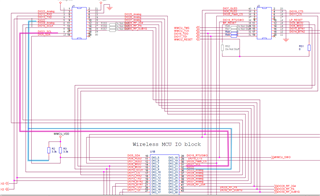
So, was DIO22 switched by mistake for DIO21_SCL (see attached image bellow, I've colored DIO21_SCL and DIO22 for easy referencing)? Or is there a reason for this? 

Thanks

  • This is a bug on the schematic. This is fixed on the Launchpads for CC1352P7. 

    The software examples etc uses DIO21 for SCL meaning that the resistor should have been connected to DIO21 and not DIO22. The boosterpacks normally have pull-ups on the I2C lines and hence the examples when these boosterpacks are used. 

  • I thought so too. Besides I've checked the schematic for the other CC1352P launchpads and CC1352P-4 is correct, with the pull up resistors connected to DIO5_SDA and DIO21_SCL. However the CC1352P-2 is also wrong, with the same bug as on CC1352P1.