This thread has been locked.

If you have a related question, please click the "Ask a related question" button in the top right corner. The newly created question will be automatically linked to this question.

LAUNCHXL-CC1350: Components between chip and switch on LAUNCHXL-CC1350?

Part Number: LAUNCHXL-CC1350
Other Parts Discussed in Thread: CC1350, CC1310, LAUNCHXL-CC1310

Hi,

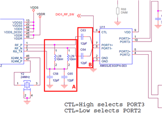
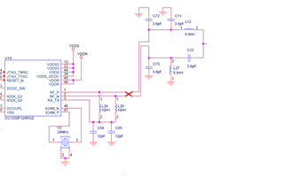
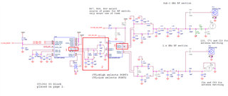
In case we don't use the switch in CC1350 (In case we use single frequency);

1) Do the components (2) between the chip and the switch need to be used, ie the components C63, C64, L29, L28, C58 and C65? If these components are not needed, should the connection (3) of the capacitors C72 and C73 of the balun be connected directly to the RF_P and RF_N pins (1)?

2) If the switch is not used, do the components in 2 need to be recalculated?, What is their function and how should I calculate it?

Thank you in advance for your answers.

Kind regards.

  • Hi,

    1. There are two sections in (2), please see the attached image for more information:
      1. Providing external biasing for the LNA. This is optional, so if you want to use the internal bias for the LNA then you can remove the components in (A). Otherwise, you will need to keep them. Please see Section 2 of SWRA640F (CC13xx/CC26xx Hardware Configuration and PCB Design Considerations (Rev F)): https://www.ti.com/lit/swra640 for more information about front-end configurations as there are performance differences based on whether you use internal/external biasing.
      2. DC blocking capacitors for the switch input (B). If you remove the switch then you can remove these two capacitors (C63 and C64).

    So, if you are removing the switch (and only using the Sub-1 GHz path, say) then you can remove C63 and C64. If you use external biasing for the LNA then keep the same values for the components in (A).

    2. As you will be removing components/the switch, you may need to adjust the matching network values after the switch to compensate for the change in impedance. Section 9 of SWRA640F (linked above) discusses the optimum load impedance required.

    Regards,

    Zack

  • Thank you for your descriptive explanation.


    Frankly, I don't know the difference between internal and external bias in terms of intended use. However, when I think that we will use external LNA bias and take into account what you said, a connection diagram like the image below emerges. I'm going to connect the LNA external bias components directly to the balun circuit, right? and this way there is no need to recalculate the balun circuit, right?

  • Is there a reason you need to use a CC1350 instead of a CC1310 if you only need to use the Sub-1 GHz path? The CC1310 would likely be more suitable if you are only interested in the Sub-1 GHz output.

  • This is how we proceed as we currently have the CC1350. If it makes more sense to use CC1310, we can consider it, but can you answer my previous question for now? Thank you.

  • I've just double-checked, the CC1350 reference design you are currently using is (or will shortly be) obsolete as the switch is discontinued, so we do not recommend it.

    Instead we recommend using a CC1310 reference design for this, which will likely answer your questions about the balun as well. The LAUNCHXL-CC1310 design does not use a switch and is matched for 868/915 MHz operation. You should be able to simply replace with the CC1350 using that design.

    Regards,

    Zack

  • Did I get it right: it works better if I use CC1310's path on CC1350's 868 MHz path. So, would there be a mismatch here between the CC1350 and CC1310's path?

    Thank you for your help.

  • We recommend using the LAUNCHXL-CC1310 reference design, but replace the CC1310 with the CC1350.

    The optimum load impedance for 868/915 MHz operation is very similar for both devices so as long as you follow the layout and stackup closely you should have the desired radio performance.

    The LAUNCHXL-CC1310 reference design files can be found here:
    LAUNCHXL-CC1310 (SWRC319): https://www.ti.com/lit/zip/swrc319

    Regards,
    Zack