


Other Parts Discussed in Thread: CC1310, CC1190
Hi,
I would like to more understand schematic of LAUNCHXL-CC13-90EU.
Could please correct me if I am wrong and add some information ?
We have CC1310 , then:
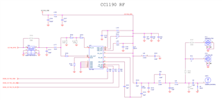
- A balun - TR1 (0850BM14E0016), use for adapte from output/input pin CC1310 complex impedance to 5ohms
- A SAW filter - FL2 (B39871B3725U410), use to filter a narrow band (868Mhz to 870Mhz). This saw filter is use for LNA ? or LNA and PA ? (Is it a good idea to put a SAW filter before PA ? of better after PA?)
- A Low Pass LC filter - C111/L111, with cut of @1779.4064Mhz, second harmonic ?
- CC1190 amplifier - U11, to amplify @27dbm
- LC ? - L25/C210. What for?
- C DC Block - C215
- LC - L26/C214, impedance matching RX/single ended
- Notch filter - C212/C24/L27
- A Low Pass LC filter - C25/L24 609.2125Mhz, ?!
- CL - A2/A3, impedence adaptation for antenna
Thanks
