This thread has been locked.
If you have a related question, please click the "Ask a related question" button in the top right corner. The newly created question will be automatically linked to this question.
Hello:
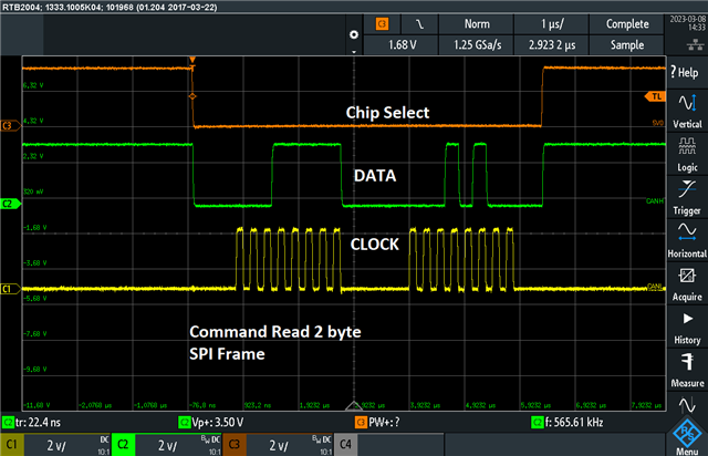
I am unable to get the RX FIFO to work properly and not able to figure out what setting is causing the problem. Data that is read back is random garbage.
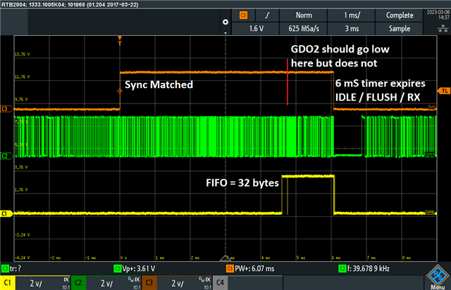
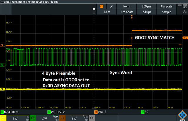
Also with the GDO2 pin configured as 0x06 to go high when a sync word is received which it does do - it however does NOT go low at the end of the message even though the length is set.
I believe these issues are related but can't figure out why / what is causing it.
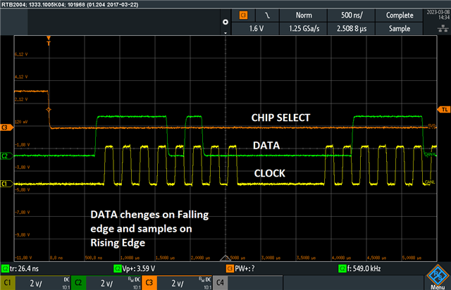
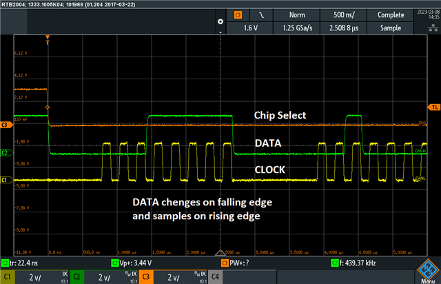
I am able to read config registers and all other items over SPI - just not the RXFIFO so it is not an SPI configuration issue (Mode, timing are all correct.)
because of this I am forced to use the Asynchronous data output and software decode the FSK signal with the microcontroller which I should not have to do.
Please advise on what could cause this IC behavior.
Regards,
Rob Tywlak
BGM Engineering services
Hi Rob,
It looks like you have encountered the RXFIFO_UNDERFLOW advisory, present in our errata: https://www.ti.com/lit/er/swrz020e/swrz020e.pdf?ts=1677578847640
What is your length filtering configured to?
Regards,
Arthur
Arthur:
That is not what I am experiencing because I am using a timer in the micro that is a little longer than the message to place the chip in IDLE and FLUSH the RXFIFO then go back to RX Mode... The message length is 34 bytes and that is set in the length register. The RX FIFO never overflows as far as I can tell.
Also I am doing a software decode of the FSK Manchester message because the FIFO does not contain valid data when it should - just reads back garbage.
I am using GDO0 set to 0x0D for asynchronous data out and the microcontroller works off of that raw FSK Demodulated Signal.
This poses a question - does the FIFO start filling only when a SYNC WORD Match has occurred or will it fill up on Noise too?
SYNC Word detection is working just not the end of the message so GDO2 set for 0x06 NEVER GOES LOW until my timer kicks the chip into IDLE and flushes the RXFIFO buffer. This was the only way I could get the chip to work. The SYNC WORD match starts the timer.
So its something else...
Regards,
Rob
Siri:
I have tried many different options and none of them make the GDO2 pin output go low at the end of the message or make the RXFIFO readable.
Remember I am using the Micro to decode the message since the RXFIFO does not work properly which is why GDO0 is set to 0x0D.
These are the current register settings:
0x06, // IOCFG2 GDO2 Output Sync matched 06
0x0E, // IOCFG1 RSSI above threshold
0x0D, // IOCFG0 GDO0 Output Pin FSK data out
0x47, // FIFOTHR
0xCA, // SYNC1
0xE1, // SYNC0
0x22, // PKLEN
0x84, // PKTCTRL1
0x00, // PKTCTRL0
0x00, // ADDR
0x00, // CHANNR
0x08, // FSCTRL1
0x00, // FSCTRL0
0x10, // FREQ2
0x12, // FREQ1
0x34, // FREQ0
0x9C, // MDMCFG4
0x17, // MDMCFG3
0x19, // MDMCFG2
0x22, // MDMCFG1
0xE4, // MDMCFG0
0x47, // DEVIATN
0x07, // MCSM2
0x30, // MCSM1
0x18, // MCSM0
0x00, // FOCCFG
0x00, // BSCFG
0x03, // AGCCTRL2
0x00, // AGCCTRL1
0x22, // AGCCTRL0
0x87, // WOREVT1
0x6B, // WOREVT0
0xFB, // WORCTRL
0x56, // FREND1
0x10, // FREND0
0xE9, // FSCAL3
0x2A, // FSCAL2
0x00, // FSCAL1
0x1F, // FSCAL0
0x41, // RCCTRL1
0x00, // RCCTRL0
0x59, // FSTEST
0x7F, // PTEST
0x3F, // AGCTEST
0x81, // TEST2
0x35, // TEST1
0x09, // TEST0
Regards,
Rob Tywlak
The radio will only put data in the FIFO after a sync is found, and when using fixed packet length mode, it will only put PKTLEN bytes in the FIFO (+ appended status bytes).
I have looked through your settings, and I am not sure where all of them comes from. For testing purposes I have used the settings provided from SmartRF Studio for the packet format and RF parameters you are using. I have marked the settings that differs from your settings to mine
// Address Config = No address check // Base Frequency = 417.848755 // CRC Autoflush = false // CRC Enable = false // Carrier Frequency = 417.848755 // Channel Number = 0 // Channel Spacing = 192.016602 // Data Format = Normal mode // Data Rate = 110.687 // Deviation = 47.607422 // Device Address = 0 // Manchester Enable = true // Modulated = true // Modulation Format = GFSK // PA Ramping = false // Packet Length = 34 // Packet Length Mode = Fixed packet length mode. Length configured in PKTLEN register // Preamble Count = 4 // RX Filter BW = 162.500000 // Sync Word Qualifier Mode = 15/16 sync word bits detected // TX Power = 0 // Whitening = false // PA table #define PA_TABLE {0x60,0x00,0x00,0x00,0x00,0x00,0x00,0x00} static const registerSetting_t preferredSettings[]= { // Customers settings {CC1101_IOCFG2, 0x06}, {CC1101_IOCFG1, 0x0E}, {CC1101_IOCFG0, 0x0D}, {CC1101_FIFOTHR, 0x47}, {CC1101_SYNC1, 0xCA}, {CC1101_SYNC0, 0xE1}, {CC1101_PKTLEN, 0x22}, {CC1101_PKTCTRL1, 0x84}, {CC1101_PKTCTRL0, 0x00}, {CC1101_ADDR, 0x00}, {CC1101_CHANNR, 0x00}, {CC1101_FSCTRL1, 0x06},// 0x08 {CC1101_FSCTRL0, 0x00}, {CC1101_FREQ2, 0x10}, {CC1101_FREQ1, 0x12}, {CC1101_FREQ0, 0x34}, {CC1101_MDMCFG4, 0x9C}, {CC1101_MDMCFG3, 0x17}, {CC1101_MDMCFG2, 0x19}, {CC1101_MDMCFG1, 0x22}, {CC1101_MDMCFG0, 0xE4}, {CC1101_DEVIATN, 0x47}, {CC1101_MCSM2, 0x07}, {CC1101_MCSM1, 0x30}, {CC1101_MCSM0, 0x18}, {CC1101_FOCCFG, 0x16},// 0x00 {CC1101_BSCFG, 0x6C},// 0x00 {CC1101_AGCCTRL2, 0x43},// 0x03 {CC1101_AGCCTRL1, 0x40}, {CC1101_AGCCTRL0, 0x91},// 0x22 {CC1101_WOREVT1, 0x87}, {CC1101_WOREVT0, 0x6B}, {CC1101_WORCTRL, 0xFB}, {CC1101_FREND1, 0x56}, {CC1101_FREND0, 0x10}, {CC1101_FSCAL3, 0xEA},// 0xE9 {CC1101_FSCAL2, 0x2A}, {CC1101_FSCAL1, 0x00}, {CC1101_FSCAL0, 0x1F}, {CC1101_RCCTRL1, 0x41}, {CC1101_RCCTRL0, 0x00}, {CC1101_FSTEST, 0x59}, {CC1101_PTEST, 0x7F}, {CC1101_AGCTEST, 0x3F}, {CC1101_TEST2, 0x81}, {CC1101_TEST1, 0x35}, {CC1101_TEST0, 0x0B},// 0x09 };
RX implementation below:
void main(void) { // initialize MCU and peripherals initMCU(); // Write radio registers registerConfig(); // Enter runRX, never coming back runRX(); } static void runRX(void) { uint8 rxBuffer[PKTLEN + 2] = {0}; // 34 data bytes + 2 status bytes uint8 rxBytes; uint8 marcstate; // Connect ISR function to GPIO2 ioPinIntRegister(IO_PIN_PORT_1, GPIO2, &radioRxISR); // Interrupt on falling edge ioPinIntTypeSet(IO_PIN_PORT_1, GPIO2, IO_PIN_FALLING_EDGE); // Clear ISR flag ioPinIntClear(IO_PIN_PORT_1, GPIO2); // Enable interrupt ioPinIntEnable(IO_PIN_PORT_1, GPIO2); // Update LCD updateLcd(); // Set radio in RX trxSpiCmdStrobe(CC1101_SRX); // Infinite loop while(TRUE) { // wait for packet received interrupt while(packetSemaphore != ISR_ACTION_REQUIRED); // Read PKTLEN bytes from RX FIFO cc1101SpiReadRxFifo(rxBuffer,(PKTLEN + 2)); // Update packet counter packetCounter++; // No CRC check is implemented, so always increase packet counter // Update LCD updateLcd(); // Reset packet semaphore packetSemaphore = ISR_IDLE; // Set radio back in RX trxSpiCmdStrobe(CC1101_SRX); } } static void radioRxISR(void) { // Set packet semaphore packetSemaphore = ISR_ACTION_REQUIRED; // Clear ISR flag ioPinIntClear(IO_PIN_PORT_1, GPIO2); }
For test purposes, I transmitted a 34 byte long packet from SmartRF Studio:
The packets were received correctly and the GPIO2 signal behaved as it should:
The data put in the FIFO will be the Manchester decoded representation of whatever is received on GDO0, so if you are only getting garbage in the FIFO, there is only garbage on the GDO0 line as well.
There is either something wrong with your HW causing bad RF performance, or there might for example be something wrong with your SPI communication (not according to spec), so that you are not running with the config you try to run with.
You need to try to figure out what this problem is, rather than trying to create a workaround for an error (GDO2 not being de-asserted) that should not happen..
Are you certain that you have configured your receiver correctly with respect to how your transmitter is configured/the packet sent by the transmitter?
Siri
Siri:
I have verified my SPI settings are correct - MODE 0, 2 MHz and have tried everything from 1 MHz to 4 MHz with no difference. I can Read back all configuration registers as well as the status byte and RSSI registers without issue - just not the RXFIFO. Its not SPI settings...
Your statement about the GDO0 being garbage also is not correct - that is how I am decoding the message... and doing so cleanly with the micro.
The SYNC word match detection is working just fine so I must have the Modem configuration correct otherwise that part would not work.
The settings came from RF studio and then I tweaked some of them to suit my application which is 115,2K symbol rate Manchester Encoded 34 byte packet.
I am also using an identical board as a transmitter to test with - only the software load is different. It has the same Micro and CC1101 on it.
Asking for help here because I have literally tried everything and why I had to resort to software decoding in the micro with the asynchronous data output and using the sync word match as a trigger to start reading in data bits. I prefer to use the RXFIFO and falling edge on GDO2 but that does not work here.
The few setting differences you mention would have nothing to do with the GDO2 pin behavior - I believe it is a timing problem or command word problem but can't figure out what specifically that is.
Try again.
Regards,
Rob Tywlak
Siri:
Tried all of your settings and it made no difference. Changed all of them to match. Still the same behavior.
Also its not likely hardware as I can get messages down to -100 dBm which is 10 dB above ambient noise... this is very near datasheet performance.
Try again because that is not it.
Regards,
Rob Tywlak
Any update on this issue?
I would like to know what could be causing this behavior.
Regards,
Rob Tywlak
Unfortunately I do not know how to proceed here.
You claim that your HW is OK, that the settings is OK and that your SPI communication is OK, but still it does not work.
For me to be able to help you further, I will need a way to reproduce the issue on my end, meaning that you will need to port this to our development platform so that I can have it fail here on my desk and then debug it.
By design, the FIFO is only filled when it finds a valid sync word.
If you cannot re-create the problem on our dev. kit, at least you need to provide me with complete logic analyzer plots that shows everything from configuring the radio, entering RX, and then reading out the FIFO (all 4 SPI lines + GDO lines are needed).
Siri
Siri:
I believe the issue is a timing problem or a missing SPI command - As I stated before I can read back the configuration registers and RSSI values so my SPI is working just fine.
One specification that is missing in the datasheet is how long does a FLUSH RX BUFFER take? So how long of a delay should I insert before issuing the RX command?
My initialization sequence is as follows:
1) Issue a RESET command on SPI and wait 10 mS - tried from 1mS to 100 mS here with no difference
2) Burst write to all configuration registers and wait 1 mS - tried various delays here with no difference
3) Place chip in IDLE and wait 100uS - tried various delays here with no difference
4) Flush RX_FIFO command and wait 1 mS - have tried up to 100 mS here with no difference
5) Place chip in RX mode
When Receiving packets GDO2 is set to go high when a sync word matches and that rising edge triggers my timer interrupt. That part works. So with sync words being detected my receiver must be configured correctly otherwise this would fail and no sync word match would occur.
The timer is set to 1 mS longer than the message length of 6.2 mS and then the IDLE command is sent, FLUSH_RX_FIFO is sent with 1 mS delay, then RX command is sent. GDO2 never goes low at the end of the message and if I read the RX_FIFO it has garbage data in it.... this is forcing me to do software / hardware decode using the Asynchronous DATA output on GDO0 set to 0x0D which works just fine so if there was a hardware issue I would not be receiving down below -100 dBm RSSI levels reliably.
If I don't issue the IDLE and FLUSH_RX_FIFO then only a single message can be received as the FIFO overflows and forces IDLE operation.
My question remains what is missing in my commands or what timing am I violating to cause this to occur?
I do not have an evaluation board to compare against here.
Regards,
Rob Tywlak
There is no need for ANY delays between SPI commands. If you issue an SRX strobe right after the SFRX, the RX strobe will be queued internally until the flushing is done.
Again, please provide me with logic analyzer plot of your SPI communication and the GDO signals if you want us to dig into this.
Siri
Siri:
Scope plots are attached showing the issue. GDO1 set to RXFIFO = 32 bytes.
SYNC word MATCH
SPI
Regards,
Rob Tywlak
Hi Rob
I tested again, and are still not able to see any issues.
Above I am sending a 34 byte long packet, and I have FIFO threshold set to 32
SYNC_RECEIVED/PACKET_RECEIVED is asserted for 4.92 ms, which corresponds to 34 bytes Manchester encoded at 110.687 kBaud (55.3435 kbps):
(34*8)*(1/55343.5) = 4.915 ms
GDO1 is asserted after 32 bytes.
Have you tried several different boards, or just one?
Are you making sure that CPIP_RDYn always is asserted before doing SPI communication?
Have you made sure that rise time, hold time etc. are according to spec on the SPI bus?
Again, I am not sure how to proceed here since I am not able to reproduce any of the issues you are seeing.
I have supported customers using the CC1101 since the chip was released, and I have never seen this issue before.
If you are always sending the same packet from your transmitter, is the data your read from the FIFO always the same?
If you do not strobe IDLE, will the GDO pin never be asserted, or does it de-assert when the FIFO overflows at 64 bytes?
Have you read back the PKTLEN register to verify that it is the correct value?
Siri
Siri:
Using 27.0000 MHz 10 ppm crystal. Baud rate is correct at 115200 symbol rate with Manchester encoding = 57.6K data rate.
Yes I am waiting for SO to go LOW before sending any SPI commands - first of which is a chip RESET.
I can only conclude the few IC's I got from our production facility must not have been stored in a dry enough environment and these are damaged because they are MSL Level 3 parts and I hot air soldered them to these boards...
So I am going to get some new ones in a dry pack and try again.
Regards,
Rob Tywlak