This thread has been locked.

If you have a related question, please click the "Ask a related question" button in the top right corner. The newly created question will be automatically linked to this question.

CC1120: Sub-1 GHz forum

Part Number: CC1120

Hello expertes.

I am a  person who is experimenting with the CC1120 in the environment shown in the picture below.
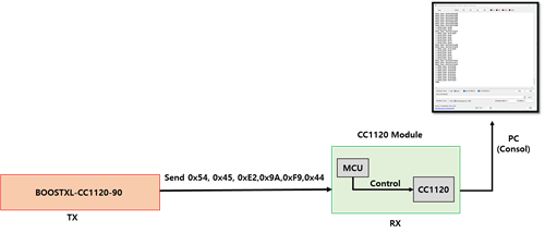
The CC1120 module acts as a RX and is composed of an mcu and a CC1120 chip, the CC1120 chip is controlled by the MCU.

The CC1120 module is manufactured, not a commercial product.

BOOSTXL-CC1120-90 is used as TX and is a commercial product of TI.

BOOSTXL-CC1120-90 interlocks with SMART RF and can transmit packets with the set Carrier Frequency through Packet TX of SMART RF in PC.

There is something I would like to ask more about in the question in the link below.

https://e2e.ti.com/support/wireless-connectivity/sub-1-ghz-group/sub-1-ghz/f/sub-1-ghz-forum/1208620/cc1120-it-looks-like-there-is-no-byte-in-rxfifo/4568273#4568273

In the above link answer, I learned that GPIO2 pin is HIGH when data is received from CC1120, and then falls to LOW while data is received.

In fact, as a result of communication using two BOOSTXL-CC1120-90, it was confirmed that GPIO No. 2 is falling while data is being received on the receiving side.

So, I coded RXFIFO to be read when the Falling edge Interrupt occurred, as informed me before when the GPIO2 pin is Falling.

But no interrupt occurred.

So, as a result of checking the GPIO pin 2, it was confirmed that it is still in the LOW state.

BOOSTXL-CC1120-90 maintains HIGH state when GPIO2 pin is checked, then turns LOW state when data is received, then returns to HIGH state.

I think there is a problem with the hardware of the CC1120 module.

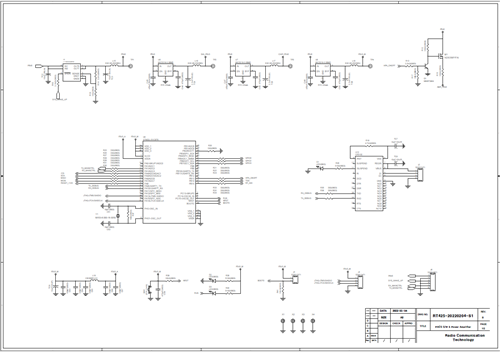
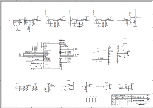
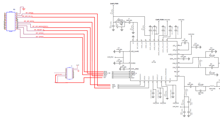
I'm really sorry, but I'm attaching the circuit diagram (Pictures and Attachments below), so if there are any mistakes in the circuit diagram, I'd appreciate it if you could let me know.

I tested both versions of the picture below, but GPIO2 was still LOW.

- Ver1.-
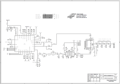
      

- VER2. -
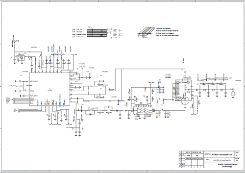
       

VER1.pdf      VER2.pdf

And the state of GPIO 0 pin was different in CC1120 Module (HIGH) and BOOSTXL-CC1120-90 (LOW).

Could you also tell me what the GPIO0 pin is doing?

The reason for the long answer in the last question is that it took a long time to reflect Falling edge Interrupt in the code for the first time

Thanks as always and any help would be greatly appreciated.

                                                                                                     - by Kim -

  • Let me see if I understand correctly.

    If you test with two BOOSTXL-CC1120-90, everything works OK, but if you use BOOSTXL-CC1120-90 as TX and your own HW as the receiver you do not receive, is that correct?

    The transmitter is using our boards, and our settings (SmartRF Studio) so it is OK.

    If the receiver does not receive, it can be caused by two things:

    1) Wrong settings

    2) Bad HW

    If you are using the same settings for the receiver as for the transmitter, you know that the settings are OK, and we are left with bad HW on the RX side.

    If you have programmed IOCFG2 = 0x06, the signal should be asserted when sync word is sent in TX and received in RX, and de-asserted when a packet is transmitted in TX and received in RX.

    If you measure on this signal both on your transmitter and your receiver, they should go high and low at about the exact same time.

    If the GDO2 signal on your receiver is low all the time, even if you are transmitting something, it means that you are not able to receive. Since we know the settings are OK (same as the TX settings) this means that there is something wrong with your HW.

    Have you followed our reference design when making your HW? This does not only mean that you should use the same components etc. but the layout of your board needs to follow our design closely.

    Hoe GDO0 should behave depends on what you have programmed the GDO0 signal to be (IOCFG0 = ???)

    Siri

  • Thank you for your sincere reply.

    You understood exactly what I wanted to ask.

    I understood that there could be something wrong with the hardware I designed.

    Additionally, I have two more questions.

    1. Does the status of GPIO2 low have nothing to do with TX packets?

    For example, if the Preamble, SYNC, and CRC of the packet transmitted by the TX side are different from the set values ​​of the RX side, I want to know whether the GPIO 2 pin is still in the LOW state.

    Or, I want to know if the state of GPIO 2 pin changes when there is a reception even though Preamble, SYNC, and CRC are different.

    2. last line in answer "Hoe GDO0 should behave depends on what you have programmed the GDO0 signal to be (IOCFG0 = ???)" 
        means that the state of the GPIO0 pin changes according to the register value of IOCFG0?

    If I understand the above question correctly, the register value of IOCFG0 in the current BOOSTXL-CC1120-90 and the manufactured CC1120 Module is the same.

    However, the state of the GPIO0 pin is measured differently.

    If so, can we see that there is a problem with the H/W?

    Sorry for asking again.

    Thank you so much for your help.

  • For how the GPIO signals works, please see section 3.4.1.1 in the User's guide. 

    As I have said before, when IOCFG2 = 0x06, this means that GPIO2 output the PKT_SYNC_RXTX signal.

    From the User guide:

    "RX: Asserted when sync word has been received and de-asserted at the end of the packet. Will de-assert when the optional address and/or length check fails or the RX FIFO overflows/underflows.

    TX: Asserted when sync word has been sent, and de-asserted at the end of the packet. Will de-assert if the TX FIFO underflows/overflows"

    That means that in RX, it must find the correct sync word to go high. It will not be able to detect a sync word at all, if there are no preamble BEFORE the sync word.

    This signal will be asserted even if there are CRC errors in the packet, it only cares about the sync word.

    Even if you have programmed the sync word to be the same as the sync word you send, a bad RF design might cause the radio performance to be poor, and you will not be able to receive the sync word even if everything is programmed correctly. This is why I have asked you if you have followed the our reference designs CLOSELY when you have made your own design.

    You also should check that your SPI communication from your MCU to the CC1120 is according to speck. Have you checked that you are able to read back the correct register values from the registers that you have configured?

    Again, I cannot tell you how the GPIO0 behave, when I do not know what value you are writing to IOCFG0.

    If you use default Studio settings, this GPIO0 = RXFIFO_THR:

    Associated to the RX FIFO. Asserted when the RX FIFO is filled above FIFO_CFG.FIFO_THR. De-asserted when the RX FIFO is drained below (or is equal) to the same threshold. This signal is also available in the MODEM_STATUS1 register

    Studio also set the IOCFG0.GPIO0_INV = 1, meaning that the signal is being inverted.

    As you can see, this is a RX signal, and is not asserted at all in TX.

    Siri

  • I am currently proceeding with hardware verification as I believe there is a problem with the hardware.

    Then, an idea came to my mind and I went ahead with it.

    It is to control the CC1120 in the CC1120 Module, which is a hardware made with MCU of BOOSTXL-CC1120-90.

    Since the MCU of BOOSTXL-CC1120-90 operates through SMART RF, I thought that if the hardware of CC1120 Module operates normally, it will be received.

    As shown in the figure below, the circuits of the BOOSTXL-CC1120-90 and CC1120 modules are connected.

    As a result of the circuit execution, unlike before, the gpio2 pin of the CC1120 Module worked and the data I sent was normally output from smartRF.

    Additionally, during the experiment, the power and clock of BOOSTXL-CC1120-90 were disabled.

    I also tried the opposite case. (The circuit was configured so that the MCU of the CC1120 Module controls the CC1120 of the BOOSTXL-CC1120-90.)

    In the case above, the gpio2 pin did not operate, but a falling edge interrupt occurred. (Occurs before x) However, no data was received.

    I think there is something wrong with the code I'm currently writing.

    Sorry to bother you, but I'll write another post, so could you please review the code one last time??

  • If I understand correctly, you say that your HW works and are able to receive packets if you are controlling it from SmartRF STudio, but the same HW does not work if you run your own code to control it, is that correct?

    I do not understand you statement:

    " the gpio2 pin did not operate, but a falling edge interrupt occurred"

    How can you get an interrupt if nothing is happening on the GPIO2 pin?

    Not sure what code you want me to review. I have already provided you with working code, and you should simply try to follow this code example as close as possible.

    You should also verify using a logic analyzer that your SPI communication is OK, and you should use a scope to verify that the SPI is according to spec.

    If your HW is OK, and your SPI communication is OK, the only thing could code should have to do to make the GPIO2 toggle once, is:

    Reset Radio

    Write all configuration registers given by SmartRF Studio

    Strobe SRX

    After these steps you should see GPIO2 go high and then low when a packet is received.

    Note that if you are not reading the FIFO or flushing it before entering RX again, you might have an overflow when the next packet is received, so the above test can only be used to verify that you receive 1 packet. Once this is confirmed, you can implement the reading of the FIFO etc.

    Siri

  • You understood exactly what I said.

    "the gpio2 pin did not operate, but a falling edge interrupt occurred"

    How can you get an interrupt if nothing is happening on the GPIO2 pin?

    I don't understand this part either. So I'm thinking maybe I've written the code wrong.

    If you have time, I'd really appreciate it if you could review it, as I'll attach the full code at the latest.

    <main code> 

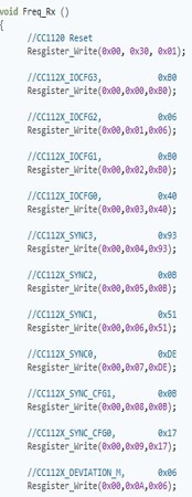
  • <Freq_RX Function> :  Reset Radio & Write all configuration registers given by SmartRF Studio (SPI communication has been verified., Since it is too long, I am attaching only part of it.)

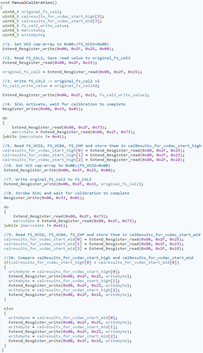
    <ManualCalibration> : The ManualCalibration function used the contents in the sample code as it is.

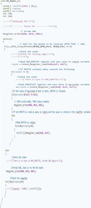
  • <RX_Radio_1> : This function reads RXFIFO whenever a GPIO2 Falling edge interrupt occurs.

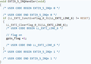
    <Falling edge interrupt detection code> : This code changes the gpio_flag variable to 1 when a falling edge interrupt occurs on the gpio2 pin.

    I know this is an unreasonable request, but I would really appreciate it if you could review it once.

                                                                                                                                                           - by kim -

  • I do not think we will get any further by me locking at your code again, as I several times have provided you the code you need (pseudo code), and since I do not know the MCU you are using.

    • Init MCU
    • Reset Radio
    • Write config registers to radio
    • Strobe SRX
    • Wait for interrupt on GPIO2
    • Read the FIFO if there are something there.

    You say that your HW works, meaning that you should think that the problem is SW related.

    I have said that if you can provide me logic analyzer plot of the SPI, I can verify that you are actually writing the registers as you think you are. Since I have not seen these plots, it might just be that there is something wrong with your SPI setup, but I cannot tell you so from looking at your code.

    Right now I can only trust that if you do for example

    Extend_Resgister_write(0x00, 0x2F, 0x25, 0x00), you set the VCO cap_array to 0x00, but there is no way for me to actually verify this, without seeing the communication that actually are sent on the SPI.

    Same goes for the interrupt. If you think you have configured a falling edge interrupt on GPIO2, and you say that you get the interrupt but nothing is happening on GPIO2, then something is obviously wrong with how you have set up your interrupt, or how the GPIO2 is connected to your MCU.

    Again, since I do not know your MCU and how to configure a falling edge interrupt on that MCU, I cannot tell you why this is not working.

    When debugging you should test the interrupt code by simply have a test signal input to the pin you use for interrupt, and then verify that every time the test signal goes low, you jump into the ISR.

    When you have this working, you can connect the input to the GPIO2 of the CC1120.

    Siri

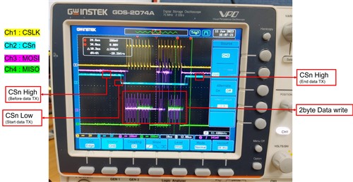
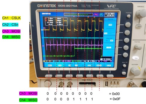
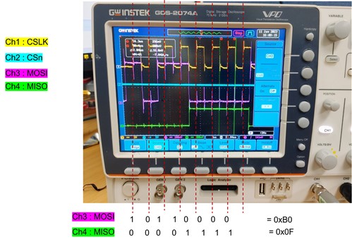
  • Here is a picture of the logic analyzer when 0xB0 is written to the IOCFG3 register (address: 0x00).


    By enlarging the above figure, we were able to obtain the same result as the figure below in byte units.


    Looking at the pictures above, I thought there was no problem with spi communication.

    Regarding the code, I think I have no choice but to do more research.

    Thanks to your help, I was able to safely resolve the data transmission.

    If I have any questions about the cc1120 chip itself in progress, I will post it.

    Thank you very much.

                                        - by Kim