Hi,
I have investigated further regarding the locked thread that has the same title as this one and, although I still cannot reproduce the success that Siri has (even though she used my own settings), I have reproduced her suggested code flow and have more information to hopefully help you determine what is going on with my setup.
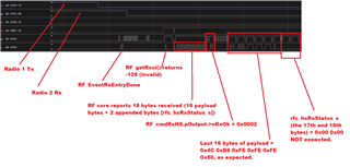
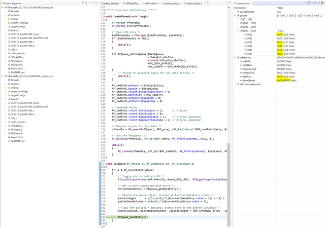
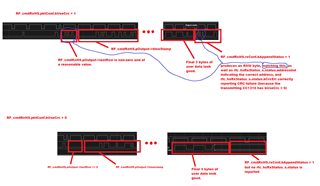
When posting the RF Rx command to the RF core, I can see, as Siri did, that the RSSI is at first invalid (-128). However, approx. 1.5ms later, valid RSSI values start being reported. When the other radio is transmitting, the reported RSSI values "jump" up to e.g. 80dBm, as I'd expect. The problem that I still have is that immediately that the call-back is entered, the reported RSSI values return to invalid (-128).
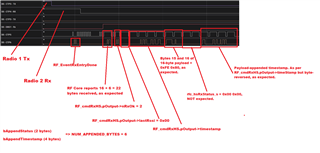
My suspicion is that this is because I only post a single RF Rx command - the RF Queue is otherwise empty as I do not know when the next transmission will be, whether it will be Rx or Tx or how long that transmission might be. When the call-back occurs, I see IRQ_RX_ENTRY_DONE and IRQ_LAST_COMMAND_DONE in the same call-back call.
- Could it be that the empty queue causes the RF core to perform garbage collection?
- If this is the case, can you recommend a simple workaround - i.e. one that preferably does not require me to add and then subsequently flush "dummy" commands to the RF core to prevent it from discarding data
- Regardless of the cause, why is it that RF_cmdRxHS.pOutput.lastRssi has a value of zero? I would expect this to always be populated before any garbage collection was done in the RF core.
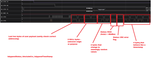
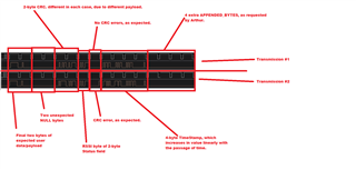
Please see the attached image for more information.
TIA,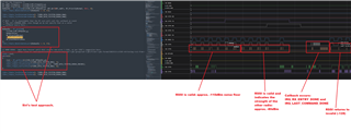
Sean.