This thread has been locked.

If you have a related question, please click the "Ask a related question" button in the top right corner. The newly created question will be automatically linked to this question.

CC85XXDK-HEADSET-RD: CC853x

Part Number: CC85XXDK-HEADSET-RD

Hi Team,

we are using the PUREPATH-WL-CFG tool to program the CC85XX_headset EVK,

Following are configuration.

1. Programmed x1 CC85XXDK-HEADSET as 1 master with bidirectional audio.

2. Programmed x2 CC85XXDK-HEADSET as slave with bidirectional audio.

Observation.

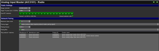
1. we are able to pair x1 slave to master and audio is bidirectional.

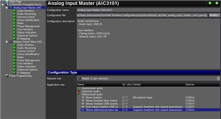
issue we are facing is both slaves are not pairing at the same.

Only first module pairs and second module is not pairing (network search LED blinks) and only second module pairs after disconnecting the first module.

  • Hi Mallikarjuanreddy, 

    Have you changed the Analog Input Master -> Radio -> Maximum slave count to 2 or more?  This value defaults to one for the out-of-box CC85XXDK Preloaded Demo.  You should also review the Help -> Configurator Help and CC85xxDK-Headset Reference Design Guide for more considerations when using multiple slave devices.

    Regards,
    Ryan

  • Hi Ryan,

    Yes, Analog Input Master -> Radio -> Maximum slave count to 2 also attached for reference.

    After reading from the Help -> Configurator Help, configured slave to 2.

    We will read HELP again re-verify the setting.

    Need your input on using Pairing Trigger options.


  • Pairing Trigger is described in the Network Pairing section of Radio Panel window from the Configurator Help Documentation.

    Network Pairing
    
    Most parts of this section are only active when autonomous operation has been selected.
    
    Maximum slave count
    For protocol masters only: Select the maximum number of protocol slaves to be supported by the network. Note that the maximum slave count should only be set as high as needed by the application:
    
    The maximum slave count by itself affects audio streaming robustness and maximum data side-channel throughput, since the timeslot is always dimensioned for this number of protocol slaves.
    Audio streaming robustness and maximum data side-channel throughput are further reduced by the number of protocol slaves actually participating in the network.
    Pairing trigger
    Select the pairing trigger:
    
    None
    For protocol master: Used for protocol slaves with fixed network ID or proximity-based pairing. This allows for button-less protocol masters such as small form-factor USB dongles.
    For protocol slave: Used when pairing is fixed, i.e. done at configuration time by specifying the protocol master's network ID in the "Default network ID" field.
    Button
    For protocol master: Used for protocol slaves that require protocol master pairing signal.
    For protocol slave: Used for any form of dynamic network pairing, either proximity-based or based pairing signal from the protocol master.
    Pairing timeout
    Specify the timeout for the pairing button. The protocol master will enable its pairing signal for this period of time, while protocol slaves will search for suitable networks for this period of time. The protocol master also disables the pairing signal as soon as a slave joins its network.
    
    Pairing mechanism
    For protocol slaves with button-based pairing only: Specify the pairing mechanism to be used:
    
    Protocol master pairing signal - The protocol master is required to activate its pairing signal (by button or the NWM_CONTROL_SIGNAL command)
    Proximity - The protocol slave must be close to the protocol master, so that the master packet's RSSI value is above the specified threshold (see below)
    Protocol master pairing signal + Proximity - Both conditions must be met
    Proximity RSSI threshold
    For protocol slaves with proximity-based pairing only: Specify the RSSI threshold for proximity-based pairing. The threshold can be found by trial and error, or by using the RFT_TXTST_PN and RFT_RXTST_RSSI commands.
    
    Default network ID
    For protocol slaves only: Specify the default network ID, i.e. the 32-bit unique address of a master device. The values 0x00000000 and 0xFFFFFFFF have special meanings and must not be used. The value 0xFFFFFFFE disables the default network ID.
    
    The protocol master's unique address can be obtained in two ways:
    
    Configurator: Connect the device using a CCDebugger, open the Flash Programming panel and read the "Device ID" from the list of connected devices.
    External host interface: Read the ID using the DI_GET_DEVICE_INFO command.
    Pairing filter 
    Specify filtering criteria when joining a network:
    
    The protocol master can prevent protocol slaves from other manufacturers from joining its network.
    The protocol slave can avoid joining protocol masters from other manufacturers, and can also require a product ID filter match on the master's product ID.
    Product ID filter mask and reference 
    For protocol slaves only: Specify the product ID filtering criteria, where the master's product ID (as configured in the master's device configuration in the "Device Identification" panel) must match the following condition:
    "Master's product ID" AND "Product ID filter mask" = "Product ID filter mask" AND "Product ID filter reference"
    "My products" matches
    Lists entries from the "My Products" list in the "Device Identification" panel that matches the filtering criteria. The stored "My Products" list does not contain information about the network role associated with the product ID. The list will therefore contain all master and slave device configurations with matching manufacturer and product ID.

    Regards,
    Ryan

  • Hi Ryan,

    From the Help menu,

    1. by specifying the different Network ID to Slave devices, able to pair both.

    2. Also Master is streaming the audio to both Slave.

    issue/Observations.

    1.Audio is streaming from one slave to master not both slaves are streaming to master.

    2. If we disconnect one slave device second slave will stream the audio.

    Please do help in understanding the protocol master/slave concept.

    Is one slave will stream to HP and one will stream to LINE ?

    we are missing any concept here ?

  • This sounds like progress, thank you for the update.  It appears that both slave devices are using the same logical channels and that this has not been changed from the "Audio Streaming" tab of the "Analog Output Slave" in PPCFG.  I recommend that you review the CC85XX User's Guide since you are using an example outside of its intended format.

    If two protocol slaves produce the same logical channel, ownership is given on a first-come first-served basis. The “next” protocol slave in line will get ownership of the logical channel when the first protocol slave leaves the network, or stops streaming of the audio channel.

    Regards,
    Ryan

  • Hi Ryan,

    Thanks for the information.

    Yes, after modification Audio Streaming" tab of the " Analog Output Slave "  x1 slave module to LEFT and x1 slave to RIGHT.

    Now we are able to stream both slave module to master.

    As of only LINE-IN works (Its mentioned only line-in enabled in codec interface not the microphone).