CC1312R7: Incorrect RSSI value measured on the 433MHz band at CC1312R1 and R7.

Part Number: CC1312R7
Other Parts Discussed in Thread: CC1312R, , CC1310

Hi,

According to my test it looks that the power detector not measuring correctly the RSSI value, on 433MHz band. The reported RSSI value is about 5-6dB higher than the signal itself.

This problem does not exist on 868 or 915MHz  

I checked it on my PCB and on your launch pad while the CC1312R and CC1312R7. using as transmitter and receiver.

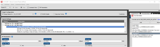
As you can see in the table below on the 433MHz for example the transmitted signal is -67.5dBm (measured by spectrum analyzer) and the Get RSSI indicate -61.5dBm (by the smart RF studio) 

On the 915MHz the RSSI level is similar to the power of the transmitted signal. 

   
Band CC1312R7 as Tx CC1312R as Rx CC1312R as Tx CC1312R7 as Rx
915 -60 -59 -64 -65
433 -32.5 -27 -67.5 -61.5

Thanks,

Shamai Yossi

  • Hi,

    • Is this only using conducted measurements?
    • Is this using the LaunchPads with a 433 MHz BOM mounted or custom hardware (and if custom hardware is the 433 MHz BOM being used)?
    • What are the radio settings being used? I can then try and replicate this using TI hardware.

    Regards,

    Zack

  • Hi,
    1) All the measurements are conducted
    2) The launchpad is with 868MHz Bom but it is the same on my PCB that using 433MHz BOM. I also done the same with CC1310 868MHz Bom and the results are good.
    3) I'm using the basic RF settings of the smart RF studio. 

  • Thank you for your reply. I was on leave earlier in the week so could not reply sooner.

    Please share the exact SmartRF Studio settings. I will then try to recreate this issue on my end as the next step. 

    If I understand your reply correctly, you have also tried using SmartRF Studio with your PCB (with the correct 433 MHz BOM) and are also seeing the issue - please can you confirm this?

    Regards,

    Zack

  • Hi I confirm that the problem is the same on my PCB with the correct 433MHz BOM.

    you can see here in the excel file attached a screen shot of the smart RF studio settings.

    433MHz RSSI measurement problem.xlsx

  • Hi Yossi,

    As this seems to be a consistent ~6 dB offset, this could be due to the RSSI offset override setting (see Section 14 of SWRA682 (Finding Settings for new PHYs for the CC13x0 and CC13x2 Family): https://www.ti.com/lit/swra682 ):

    • The RSSI offset override using the 868/915 MHz 50 kbps PHY as the starting point is: (uint32_t) 0x000188A3
    • If you start with the 433 MHz 50 kbps PHY, the RSSI offset override is: (uint32_t) 0x000688A3
    • This suggests that the RSSI offset override being used is incorrect.

    If I am reading the Excel file you provided correctly, you are starting with the 868/915 MHz PHY settings and then modifying the output frequency for 433 MHz operation.

    Please can you measure using the 433 MHz 50 kbps PHY settings as the starting point?

    Unfortunately it looks like the PA table settings in SmartRF Studio have not added additional output power steps below +13 dBm for 433 MHz operation for the CC1312R7.

    For future reference (if you wanted to make additional changes), to use the correct PA table for the CC1312R7:

    • Select the CC1312R7 in the initial menu (Proprietary mode).
    • Select LP-CC1352P7-4 from the Target Configuration -> RF Design Based On drop-down menu.
    • Select Settings -> Custom Target Configuration from the top bar.
      • The Output Power tab provides the correct PA Table for 433 MHz operation on the CC1312R7.
    • Remove the I/O Signals (the "X" on the right-hand side of each DIO configuration).
    • Save the configuration for later use.

    For convenience, you can use the provided configuration files below:

    /cfs-file/__key/communityserver-discussions-components-files/156/433MHz_5F00_CC1312R7.zip

    To use this config file:

    • In the top bar: File -> Open Cfg
    • Select target_433MHz_CC1312R7.xml
    • Select 433MHz_CC1312R7 from the Target Configuration -> RF Design Based On drop-down menu.
    • When a 433 MHz PHY is now selected, the TX Output Power drop-down menu should now have settings from +13 dBm to -11 dBm.

    Please note that there is a national holiday and I will not be able to reply until Tuesday 2nd April next week.

    Regards,

    Zack

  • Hi Zack,
    it looks that the offset override helps us.   
    I try it with Smart RF studio, and it is working as expected.

    It doesn't matter if we are working with the 868MHz or with 433MHz on the beginning.

    As for the output power I try to update the configuration file I done the 2 first steps. and didn't succeed to continue with step no#3:

    • Select 433MHz_CC1312R7 from the Target Configuration -> RF Design Based On drop-down menu.
    • When a 433 MHz PHY is now selected, the TX Output Power drop-down menu should now have settings from +13 dBm to -11 dBm.

    Thanks,

    Shamai Yossi

  • Hi,

    Glad to hear that the root cause may have been found.

    If you try the first method (making your own configuration file), do you successfully get the range of output power settings?

    • Select the CC1312R7 in the initial menu (Proprietary mode).
    • Select LP-CC1352P7-4 from the Target Configuration -> RF Design Based On drop-down menu.
    • Select Settings -> Custom Target Configuration from the top bar.
      • The Output Power tab provides the correct PA Table for 433 MHz operation on the CC1312R7.
    • Remove the I/O Signals (the "X" on the right-hand side of each DIO configuration).
    • Save the configuration for later use.

    Regards,

    Zack