This thread has been locked.

If you have a related question, please click the "Ask a related question" button in the top right corner. The newly created question will be automatically linked to this question.

LP-EM-CC1314R10: How to implement RF multiple transmitter and single receiver (LP-EM-CC134R10)

Part Number: LP-EM-CC1314R10
Other Parts Discussed in Thread: SYSCONFIG, CC1314R10, CC1354P10, LP-XDS110ET

Tool/software:

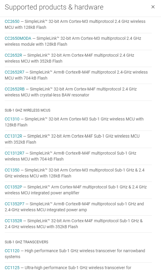
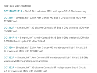
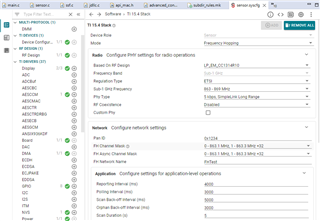
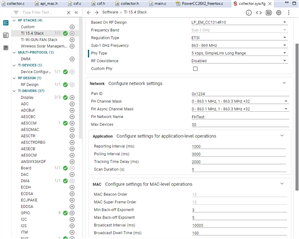
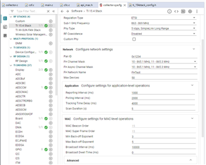
Hi, I'm trying to work with LP-EM-CC1314R10 multiple RF transmitters and a single receiver. Is there any possible way to receive from multiple transmitters without payload loss at the RF receiver end and how to implement configurations for both transmitter and receiver to achieve the scenario? 

  • Hi Mani,

    could you give us more details on the communication that you want to implement?

    Which communication pattern do you want to achieve?
    Which frequencies do you want to use?
    How many devices to you want to connect and which is there role?
    Which are the requirements regarding package loss, refresh rate and so on?

    Kind regards,
    Theo

  • Hi Theo,

    We are using it for the industrial purpose where multiple RF-transmitters (maximum 100 devices) will send different sensor data to one RF receiver over the Sub - 1GHz frequency.

    Regards,
    Manivel

  • Hi Manivel,

    did you consider using Ti15.4-Stack: https://www.ti.com/lit/an/swra782/swra782.pdf?ts=1726483058458

    In Table 6.2.1 Sub1G you can see the results of our stability test with 100 nodes.

    Does it fulfill your requirements?

    Kind regards,
    Theo

  • Hi Theo,

    Thanks for your suggestion.
    By following the reference manual, we are running the "collector_sm" and "sensor_sm" examples. Currently we are trying to do PoC with 3 "LP-EM-CC1314R10" launchpads, one as a collector and the rest two launchpads as a sensor.

    Following are our observations:

    1. When sending the data from just 2 sensors to one collector, we are having  issue like the packets of one sensor are not received by the collector after some time . 
    2. Do we need to change some configuration for adding more sensors?  (Note we increased the Transmit power to 12 dBm and the reporting interval to 500 ms on both the collector and sensor).

    We even tried to change the PAN ID in the .sysconfig file for collector, but it didn't change and i verified in collector CUI. 

    Kindly add your suggestion. 


    Regards,
    Manivel

  • Hi Manivel,

    great that you started testing.

    I replicated your setup here: one CC1314R10 collector and two CC1314R10 sensors with all devices changed to a  reporting interval of 500 ms and a polling interval of 300 ms. I can not see any disconnections or missed messages after letting it run for 20 min on my desk, looking at the terminal application.

    Can you explain me your setup in more detail:
    1. How do you observe the sent and received packets?
    2. How long do you let it run to see problems?

    There is no changes required for adding more sensors but be aware that depending on the data you want to send and depending on the number of sensors you might need to adjust the reporting and polling intervals.

    Kind regards,
    Theo

  • Hi Theo,

    Thanks for your reply. We never changed the polling interval in our setup (kept as default 2000); we only updated the transmit power and reporting interval on both sides.
        
        1. On the sensor side transmitting data, we have one byte for the board ID and two bytes for the sequence number
    In the collector end, we are parsing the board ID and sequence number. We are printing the results every 10 seconds on the collector side as well (on separate UART).
        
        2. For us, we had an issue after 1.5 hours of running. i.e., a security error is shown in the collector CUI terminal. 
    Note: There are two observations that the sensor board is permanently disconnected or it will be reconnected automatically after 1 hour (i.e., the collector stops receiving data somewhat around the seq_No. 10000 and will receive the data from seq_No. 20000).
        
    For the confirmation, you have also used the same non-beacon mode, and you have changed the poll and reporting time only in the "collector_sm" and "sensor_sm" examples. How have you transmitted the data continuously from the sensor to the collector?.

    Regards,

    Manivel

  • Hi Manivel,

    the security error could be related to the frame counter so if you run further tests you could undefine the security define to prevent that.

    Do you know if the missing data is do to the sensor no longer transmitting or the collector no longer receiving?
    You can observe this using a packet sniffer: https://www.ti.com/tool/download/PACKET-SNIFFER-2/1.9.0

    I was testing in non-beacon mode using the collector and sensor project with changed intervals and observing the devices in the network from the terminal application.

    I will setup a test with the sm projects. Please let me know if you have more details.

    Kind regards,
    Theo

  • Hi Theo,

    Thanks for your response.

    Regarding the sniffer, I think the launchpad we are using (LP-EM-CC1314R10) is not supported by the sniffer application.

    In our setup, we are actually utilizing the command "Smsgs_cmdIds_toggleLedRsp" to transmit our custom data. When we tried to add the new command and transmit with the "Sensor_sendMsg" API, the data was not received on the collector side (we added the new command on both sides).
    So is there a possible way to transmit our custom data with different intervals? Did you transmit any data between the snsors and collector frequently and observe the results on your setup?

    Note:
    When we changed the operating mode to "frequency hopping,"  the collector is loacked in the "vPortFree - configASSERT( heapBLOCK_IS_ALLOCATED( pxLink ) != 0 );" due to the heap memory issues after receiving 10000 packets.

    Regards
    Mani Vel

  • Hi Theo,

    From afternoon, the sensor status is always in orphaned state. We even tried by flashing the "collector" and "sensor" examples without any modification but the sensor is still not connecting with the collector, the status is showing as orphaned state only.

    What could be the reason?. can you kindly help us?.

    Collector and sensor CUI log

    Regards,
    Mani Vel

  • Hi Manivel,

    did you already go through the introduction that we offer in our SimpleLink Academy (https://dev.ti.com/tirex/explore/node?node=A__AchrNsM7a4pBwreGXXho7Q__com.ti.SIMPLELINK_ACADEMY_CC13XX_CC26XX_SDK__AfkT0vQ__LATEST) ?

    If a sensor connects to a collector for the first time it saves the address of the device it is connected to. If you want to reset the devices you need to erase the flash. You can do so by holding BTN-2 pressed, press reset and then release BTN-2 after the red LED stopped blinking. This ensures that you start all your tests with a "fresh" device.

    A sensor is in orphaned mode when it looses the connection to the collector (e.g. if the network is set up and you unplug the collector). If you reconnect the collector and reset the sensor it will rejoin the network.

    Please try to follow the SimpleLink Academy and start with the plain sensor and collector projects. Then we can move to using the other available features depending on your needs.

    Kind regards,
    Theo

  • Hi Theo,

        Thanks for your valuable help.
        
        We already started working with a basic sensor and collector example. We also found the page for adding the custom message with this refered link: dev.ti.com/.../node and we will refer this also.
        
        We will ask for your help with any queries.

    Regards,
    Mani Vel

  • Hi Mani Vel, 

    the procedure to define a custom message and how to implement the sending and receiving is explained in the second lab: https://dev.ti.com/tirex/explore/node?node=A__Ad2.9fPbq0Ip1JEbNHZlww__com.ti.SIMPLELINK_ACADEMY_CC13XX_CC26XX_SDK__AfkT0vQ__LATEST 
    Please let me know if you were successful in implementing a custom message.

    Once you followed the labs you can move to the secure commissioning examples (sensor_sm, collector_sm) which implement the secure features described here: https://dev.ti.com/tirex/content/simplelink_cc13xx_cc26xx_sdk_7_41_00_17/docs/ti154stack/html/ti154stack/secure-commissioning.html All the other functionality from the sensor and collector project stays the same so you can in the same way implement a custom message.

    Please note that the implemented trigger for the secure key refreshment should be modified by you to be triggered for all devices by either a timer or message exchange, etc. This is necessary to keep the devices connected.

    To observe the send packages you could use a launchpad that is supported with our packet sniffer firmware: https://dr-download.ti.com/secure/design-tools-simulation/calculation-tool/MD-r3ewsc0OIX/1.10.0/SmartRF_Packet_Sniffer2_1.10.0.zip

    Can you tell me what kind of device you are building?

    Kind regards,
    Theo


  • Hi Mani Vel,

    for the packet sniffer you need to use one of the supported boards:

    Another debugging option is to implement a second UART (https://e2e.ti.com/support/wireless-connectivity/sub-1-ghz-group/sub-1-ghz/f/sub-1-ghz-forum/1415402/lp-em-cc1354p10-adding-uart-interruption-to-wi-sun-coap-project).

    Kind regards,
    Theo

  • Hi Theo,

    Thanks for your support.

    From your list we could not find the launchpad that we are having (LP-EM-CC1314R10).
    However when searching on online there is a Ti's packet sniffer V2.18.1, which supports the MCU that we are having CC1314R10..
    Link : https://www.ti.com/tool/PACKET-SNIFFER#tech-docs

    So, Would you please verify if we are able to utilize our launchpad (LP-EM-CC1314R10) as a packet sniffer or not?

    If not we will ask our team to get us a new launchpad.

    Best Regards,
    ManiVel.

  • Hi Mani Vel,

    we are not supporting the old versions of the packet sniffer anymore and the CC1314R10 is also not supported by it.

    If you want to use the packet sniffer you should use the latest version of SmartRF Packet Sniffer 2 v1.10.0: https://dr-download.ti.com/secure/design-tools-simulation/calculation-tool/MD-r3ewsc0OIX/1.10.0/SmartRF_Packet_Sniffer2_1.10.0.zip
     
    You also need to buy a compatible launchpad from the list of supported hardware because it is not compatible with CC1314R10.

    If you are just looking for a way of simple debugging you could also use prints you with the sensor cui that is implemented in the projects.

    ____


    Did you continue with the procedure that I suggested before?

    the procedure to define a custom message and how to implement the sending and receiving is explained in the second lab: https://dev.ti.com/tirex/explore/node?node=A__Ad2.9fPbq0Ip1JEbNHZlww__com.ti.SIMPLELINK_ACADEMY_CC13XX_CC26XX_SDK__AfkT0vQ__LATEST 
    Please let me know if you were successful in implementing a custom message.

    Once you followed the labs you can move to the secure commissioning examples (sensor_sm, collector_sm) which implement the secure features described here: https://dev.ti.com/tirex/content/simplelink_cc13xx_cc26xx_sdk_7_41_00_17/docs/ti154stack/html/ti154stack/secure-commissioning.html All the other functionality from the sensor and collector project stays the same so you can in the same way implement a custom message.

    Please note that the implemented trigger for the secure key refreshment should be modified by you to be triggered for all devices by either a timer or message exchange, etc. This is necessary to keep the devices connected.


    Kind regards,
    Theo


  • Hi Theo,

    As you mentioned, we are now working with the "collector" and "sensor" examples. We modified only the PANID and increased the transmit power to 12 dbm. 
        
    As per your suggestion, we configured another UART and printed the "Smsgs_cmdIds_sensorData" command received count on the collector side. 
        
    Our observation is that we had tested with 1 sensor and 1 collector within the range of 2 meters. It was working fine, but when we tried to increase the range between collector and sensor by 2 floors (30 m), the collector couldn't be able to receive more than 100 packets. In collector CUI, the device status of a sensor is "!Responding". 
        
    Please kindly help us to resolve the issue.

    Regards,
    Manivel

  • Hi Mani Vel,

    this sounds like you are getting out of range. Which phy are you using?

    You could use SmartRF Studio (https://dr-download.ti.com/secure/design-tools-simulation/calculation-tool/MD-EekuFuy77r/2.31.0/smartrftm_studio-2.31.0.zip), select the phy that you are using and use on board in packet tx and the other one in packet rx to see if it is a phy level issue. 

    The range fully depends on the selected phy, the tx power and the obstruction that you have. The maximum tx power of your device is 14 dBm.
    If you need a higher tx power you can switch to one of our p devices e.g. CC1354P10 where you can reach 20 dBm.

    Kind regards,
    Theo

  • Hi Theo,

    Thanks for your support.
        
    In both "collector" and "sensor" examples, PHY which we are using, is "50 kbps, 2-GFSK." In the CCS IDE.sysconfig file, I can change PHY to the few listed, but in SmartRF Studio 7, I can check more than listed in the.sysconfig file. 
        
    Using the "Smart RF Studio 7" tool, I need both the launchpads to be in live debugging (using LP-XDS110ET debugger * 2). Is our understanding correct?


    Regards,
    Manivel

  • Hi Manivel,

    for TI15.4 only the Phys shown in sysconfig are supported. In SmartRF Studio all Phys that the device can support are shown. They correspond to different software stacks.

    Please use for the testing the same Phy that you want to use in sysconfig for TI15.4.

    For testing you need to connect both launchpads to an XDS110 and then connect them over usb to a computer. When you open SmartRF Studio it then highlights the device that you connected. You need to select the same phy and then you can test with one board in packet tx and the other board in packet rx.

    Kind regards,
    Theo

  • Hi Theo,

    Currently we have only one LP-XDS110ET debugger so we couldn't test the smartRF Studio . Now we have ordered additional debugger  .


    In the meantime, we had performed a long-run test (one collector and two sensors) lasting around two days and made some changes to the band (ETSI), PHY (5 kbps, SimpleLink Long Range), mode (NBCN), and interval mentioned in "Application Note: TI 15.4-Stack Software. - Table 6.2.1 Sub1G".

    Observation on long-run testing:

    1. Even after two days, the collector is still able to receive sensor data from one of the sensors that is in line of sight (the sensor antenna and collector antenna facing each other) with an error rate of 1%.

    2. The rest of the sensor antenna has been angled sideways toward the collector antenna with the 85% error rate. The sensor data is continuously being transmitted at the sensor end even though the collector was unable to receive any packets from this sensor after the test lasted for four hours.

    Please kindly help us to resolve the issue.

    Additionally, where we can find the details about the large network stability test , mentioned in the  Table 6.2.1.
     like

    1. Which PHY that they have configured for testing the 100 nodes (in FCC and ETSI).
    2. What is the maximum distance that they have placed the sensors.

    3. Reporting time 20s means every 20s only the sensor data is transferred - is that our understanding correct?.


    Regards,
    Manivel

  • Hi Manivel,

    the LP-XDS110ET is the debugger including the Energy Trace that can be used with Code Composer Studio to visualize the boards energy consumption.

    Please give me the following information so that I can assist you:
    1. I understood that you setup a test with 1 collector and 2 sensors. Which software examples are you running on the collector and on the sensors?
    2. Please provide me a screenshot like the following example for the collector and the sensors, so that I can check all the 15.4 settings that you are using.

    3. Which transmit power do you use for the collector and the sensors?
    4. Where are the devices placed (distance, obstructions)?
    5. How do you count sent and received messages? Did you also look at the RSSI?
    6. Have you made any changes to the examples?


    I can already answer:
    1. Going through the lines of the table the configurations are:

    • FCC, 5 kbps Simple Link Long Range, Beacon Mode, 75 Nodes
    • FCC, 5 kbps Simple Link Long Range, Non Beacon Mode, 100 Nodes
    • FCC, 50 kbps 2-GFSK, Frequency Hopping Mode, 75 Nodes
    • FCC, 50 kbps 2-GFSK, Frequency Hopping Mode, 100 Nodes
    • ETSI, 200 kbps 2-GFSK, Non Beacon Mode, 100 Nodes

    2. For the Large Network Test the bards are placed in a rack setup and different network topologies are enforced by the software. This is only the software evaluation test for 15.4 Stack. The board hardware is characterized in various other tests. E.g. the boards antenna characteristics can be found here: https://www.ti.com/lit/an/swra496a/swra496a.pdf pages 178, 183. 

    3. This depends on the mode that you are using. In our User's Guide the different modes are explained in detail: https://dev.ti.com/tirex/explore/node?node=A__AITUIbVTzCdD7w7KebQ-qA__com.ti.SIMPLELINK_CC13XX_CC26XX_SDK__BSEc4rl__LATEST

    Please answer the points above and I will help you to fix your setup.

    Kind regards,
    Theo

  • Hi Theo,

    1. We have been using the "collector" and "sensor" examples.


    2. I had attached the .sysconfig image of both collector and sensor examples, followed by,

    collector:

    Sensor:

    3. Now the transmit power we are using is 12 dBm for both the collector and sensor.
    4. Sensor-1 distance 20 m antenna towards collector antenna and Sensor-2 distance 15 m antenna sideways to the collector antenna.
    5. In the collector and sensor example, by default the temperature sensor data has been transmitted from the sensor and received by the collector. 

    In the collector  "dataIndCB" function, there is a case "Smsgs_cmdIds_sensorData," which receives all the sensor data. In this case, we add an incremental count and transmit the count in UART.

    In the Sensor  "sendSensorMessage" function, the sensor data's are periodically transmitted from the sensor. In this functionality, we made an incremental count and transmit the count in UART.

    For RSSI, Sensor-1 ranges between 50 and 60 and Sensor-2 ranges between 65 and 75, verified in the collector CUI.

    6. For testing the range, we had newly imported these examples and only added UART configurations and incremental count transmitting through UART. 

    Regards,
    Manivel

  • Hi Manivel,

    from your sysconfig settings I can spot that you set the Polling Interval to 20000 ms.
    When you click in sysconfig on the question mark right after "Polling Interval (ms)" you will see the following hint: The polling interval must be within the range of the MIN_POLLING_INTERVAL and MAX_POLLING_INTERVAL defined in the sensor project. By default, that range is from 1,000 to 10,000 ms. 

    1. I would recommend you to adjust the polling interval to be in the specified range (e.g. 9000 ms). You can leave the reporting interval set to 20000 ms.

    2. The RSSI looks good so please test again with the adjusted reporting interval as it might be a synchronization issue that occurs because the value is out of spec.

    3. Can I ask you for which product this is for?

    You can also click on the question mark next to reporting interval for a good explanation. Please let me know if that answers the questions or if there is following questions.

    Kind regards,
    Theo


  • Hi Theo,


    We made our setup according to the 5th configuration (ETSI -  Poll :20s/ Track: 100s/ Report:20s  - NBCN),

    1. I would recommend you to adjust the polling interval to be in the specified range (e.g. 9000 ms). You can leave the reporting interval set to 20000 ms.

    >> Ok. We will reduce the polling interval to 9s.

    2. The RSSI looks good so please test again with the adjusted reporting interval as it might be a synchronization issue that occurs because the value is out of spec.

    >> We will test with new configuration.

    3. Can I ask you for which product this is for?

    >> We are building a kind of Gateway application where it receives data from multiple transmitter devices. So we are testing the maximum range/power/nodes with our launchpad devices.
    >> Currently we are testing in the NBCN mode with long range PHY setting in the Ti 15.4 stack "5 kbps, SimpleLink Long Range ".
    >> Also in some application notes they recommended the frequency hopping mode for better performance. Can you add your thought on this?

    Regards,
    Manivel

  • Hi Manivel,

    that's great, please let me know how the tests are going.

    For frequency hopping we have two relevant app notes:
    https://www.ti.com/lit/wp/swry025/swry025.pdf?ts=1727779049082&ref_url=https%253A%252F%252Fwww.google.com%252F
    https://www.ti.com/lit/an/swra529a/swra529a.pdf?ts=1727779050212&ref_url=https%253A%252F%252Fwww.google.com%252F

    It will in any case make your network more robust to jamming on single channels and as you can see in the app notes it lets you use higher transmit power under FCC regulations.

    Kind regards,
    Theo

  • Hi Theo,

    Thanks for your suggestion.

    We had modified the polling interval to 9000 ms and tested for a day. In that there is an error rate of 0.01% and still both sensor data are able to be received by the collector.

    For frequency hopping, you mentioned FCC regulation, but we are working on ETSI regulation. Is frequency hopping effectively used by ETSI regulation?

    To achieve the long range, we will test the PHY one by one with the help of the "Smart RF Studio 7" tool once the placed order debugger arrives.

    Regards,
    Manivel

  • Hi Manivel,

    good to hear that it works now as expected.

    I will check the details for the certification with our experts and come back to you.

    Please keep me updated.

    Kind regards,
    Theo

  • Hi Manivel,

    regarding ETSI certification I would like to add the following information.

    The 15.4 stack can be used with NBCN and FH mode on the ETSI regulation. Within the ETSI spec you should review the section called Adaptive frequency agility (EN 300 220-1 section 5.21.4) if you plan on using FH mode of the 15.4 stack. The ETSI specification mentions a FHSS mode, but gives very little to no advantage versus low duty cycle device or LBT+AFA device.

    More info can be found in the last response of this thread: https://e2e.ti.com/support/wireless-connectivity/sub-1-ghz-group/sub-1-ghz/f/sub-1-ghz-forum/774299/cc1310-proprietary-slow-frequency-hopping-implementation---etsi-en-300-220-compliance

    Kind regards,
    Theo

  • Hi Theo,

    Thanks for your valuable effort. Me and mani vel are working on this. We will update you on our further activity.

    Best Regards,
    Muniyappan R M

  • Hi Muniyappan,

    thank you for the update. Let me know if I can further assist you.

    Kind regards,
    Theo

  • Hi Theo,

    We now received another debugger. So will test the different PHYs in the smartRF studio.

    To inform you again we are building a product like gateway(a Collector) and sesnors where the Gateway should receive data from multiple sensors over a long range. The frequency band we are using is 868 Mhz  (ETSI standard). We are majorly focusing on long distance and low power on sensor side.

    We have some doubts and listed in the following,

    1. As you mentioned earlier, 

    for TI15.4 only the Phys shown in sysconfig are supported. In SmartRF Studio all Phys that the device can support are shown. They correspond to different software stacks.

    Please use for the testing the same Phy that you want to use in sysconfig for TI15.4.

    >> So we need to test only 3 PHYs i.e available in the TI stack for ETSI using the smartRF studio?

    Is our understanding correct?.

    2. When reading the user guide, we understand the polling interval means, how often the sensor is polling the data from the collector. And the collector will set the polling and reporting interval to a sensor when it is connecting to a network (i.e Whatever we are configuring in the sensor.syscfg is only default value and collector will send the values configured in the collector.syscfg to the sensor when it is joining the network). 

    a. In our case the reporting interval may vary based on the sensor that the user is using, So can we configure different reporting interval to a sensor on a multi sensor network?.
    b. If yes, do we need to change the polling interval to each sensor as well?

    Kindly help us to understand.

    Best Regards,
    Muniyappan R.M


  • Hi Muniyappan,

    thank you for the update.

    1.  When you select in .syscfg your region then it will show you the phy's that we tested and if it meets your use case this is recommended to use. The phy which will give you the longest range is 5 kbps, SimpleLink Long Range. If you need to use a custom phy then you can enable this option in .syscfg in the radio settings but if it is not necessary I encourage you to stay with our recommendation. You can test the phys with SmartRF Studio.

    2. Your understanding is correct. The configuration of the sensor will be set by the configuration message received from the collector after joining the network. The polling interval is also used to sync up the devices in the network. I will follow up with R&D if there is an option to configure different intervals or if this will unsyc the devices and come back to you next week.

    Let me know how the phy testing proceeds.

    Kind regards,
    Theo

  • Hi Muniyappan,

    checking with our experts you could look into implementing on the sensor side to ignore the reporting interval of the configuration message.

    This means the sensors need to have the same polling interval which needs to be set by the configuration message of the collector. This is necessary because it is used for synchronization of the network (the sensors needs to wake up at the right time). 
    But you can ignore the reporting interval of the configuration message and configure it for each sensor to a different value as the collector is always listening.

    We have no example application for that and it is not a tested feature. If you look into this and experience any issues please let me know and I'll assist you in debugging it.

    Kind regards,
    Theo

  • Hi Theo,

    Thanks for your response.

    checking with our experts you could look into implementing on the sensor side to ignore the reporting interval of the configuration message.

     - We will try to implement this logic. Additional question,  Do the sensor need to send its desired reporting interval back to the collector?

    Regarding out range testing ,we have tested with the Long range PHY's mentioned in the studio and following are our observations,

    50 packets , 20 byte data length , 500ms interval
    PHY Distance
    50m 100m 200m
    50 kbps, 25 kHz Deviation, 2-GFSK, 100 kHz RX Bandwidth All packets received 49 received , 1 crc error No data received
    SimpleLink Long Range, 5 kbps (20 ksps), 5 kHz Deviation, 2-GFSK, 34 kHz RX Bandwidth, FEC = 1:2, DSSS = 1:2 All packets received All packets received Only 20 packets received .
    12 - CRC error
    8 - Good
    SimpleLink Long Range, 2.5 kbps (20 ksps), 5 kHz Deviation, 2-GFSK, 34 kHz RX Bandwidth, FEC = 1:2, DSSS = 1:4 All packets received All packets received Only 41 packets received .
    4 - CRC error
    37 - Good

    When going beyond the 250 or 300m we are not receiving any data. Our customer requirement is at least 700m of range . Can you help us to improve the range?.

    Note: 

    1. we tested with the on board PCB antenna. Now we are planning to connect external antenna and test again.

    2. We are currently testing with 5kbps and 2.5kbps PHYs, since it is mentioned as long range. Is our understanding is correct? or is there any PHYs that is good to test the long range?

    *** We have also some quires with the collector and sensor example, I have posted on the separate thread  : https://e2e.ti.com/support/wireless-connectivity/sub-1-ghz-group/sub-1-ghz/f/sub-1-ghz-forum/1433234/lp-em-cc1314r10-orphan-sensor-rejoin-issue---orphan-scan-not-triggered

    Regards,
    Muniyappan R.M

  • Hi Muniyappan,

    good to hear that the testing continues.

    The reporting individual reporting interval does not need to be send back to the collector. The collector is always listening if it is not in tx. Please let me know about how that goes when you implement it.

    RANGE

    To help you achieve the longest range let me list your RF parameters again. Yo are using:
    - 2x CC1314R10 - one as collector and the other one as sensor
    - TI 15.4 Stack in non-beacon mode -> after network forming communication on only one channel
    - ETSI channels 0 - 4
    - TX power: 12 dBm
    - PCB antenna
    Please correct this information if anything has changed or is missing.

    I have a few questions regarding your testing environment:
    1. Are the devices in line of sight and do you have interference in between them?
    2. What is the noise floor in your testing environment (if you haven't checked it you can use SmartRF Studio with the device in continuous RX to measure it)?
    3. At which height over ground do you test the devices and are the devices oriented towards each other?
    4. Does the 2.5 kbps SimpleLink Long Range PHY fulfills your requirements of data rate or do you have higher requirements for the data rate?

    In general the 2.5 kbps SimpleLink Long Range PHY in combination with the highest tx power (for CC1314R10 = 14 dBm) will result in the longest range. 

    You can get a range estimation with our range calculation excel tool: https://dr-download.ti.com/software-development/support-software/MD-Z2giRsrpoF/01.00.00.0D/swsc002d.zip
    The settings that you need to select is the "CC_Antenna_DK2_#9" for the pcb antenna and the "CC13xx - 2.5 kbps (LRM), Sub-1 GHz" for the 2.5 kbps SimpleLink Long Range PHY.

    Overall it is possible to achieve the 700 m and more that you require and it sounds like you have a pretty high noise floor. 

    I'm looking forward to your answer and we'll help you to find a working solution.

    Kind regards,
    Theo


  • Hi Theo,

    Thanks for your response.

    Please correct this information if anything has changed or is missing.

    >> The tests were done using the smartRF studio with two LP-CC1314R10 boards in Packet-Tx and Packet-Rx modes since we need to fix the PHY which suits for our requirement before going to the collector and sensor example.

    Now regarding your questions,
    1. Are the devices in line of sight and do you have interference in between them?

    >> The devices are in the line of sight and We are currently tested with some interference.


    2. What is the noise floor in your testing environment (if you haven't checked it you can use SmartRF Studio with the device in continuous RX to measure it)?

    >> When running the SmartRF Studio with the device in continuous RX mode we are getting some RSSI graph. What is the ideal RSSI value for a good testing environnemt?; 


    3. At which height over ground do you test the devices and are the devices oriented towards each other?.

    >> Yes both the devices are in same height over the ground and oriented each other.


    4. Does the 2.5 kbps SimpleLink Long Range PHY fulfills your requirements of data rate or do you have higher requirements for the data rate?

    >> Yes.

    In general the 2.5 kbps SimpleLink Long Range PHY in combination with the highest tx power (for CC1314R10 = 14 dBm) will result in the longest range. 

    >> Thanks Theo. Now we are planning to run the tests again (with the smartrf studio only ) in the more noiseless environment possibly with the external antenna (Since we will use the same antenna in our product) and update you about the results.

    Similarly you can also suggest us about the configuration parameters to achieve the long range with the CC1314R10 board.

    We have some questions,

    1.  The smartRF studio is used to identify the ideal PHY for our application and there we could not select the NBCN/BCN/FH modes - right?.

    2. Once we fixed the PHY using SmartRF studio,  and configuring the the same settings in the collector and sensor example using Custom PHY option will result the same range irrespective of the  Beacon/Non-Beacon/Frequency hopping modes?. Or there will be the difference ?.

    3. Is there any range test conducted with the CC1314R10 board and is there any documents available?.

    you have already shared us about the stability test results,

    But we focused more about range. So Is there anything you can help us?

    Best Regards,

    Muniyappan R.M

  • Hi Muniyappan,

    let me first answer you questions:

    1.  The smartRF studio is used to identify the ideal PHY for our application and there we could not select the NBCN/BCN/FH modes - right?.
    - This is correct. The mode is not impacting the range.

    2. Once we fixed the PHY using SmartRF studio,  and configuring the the same settings in the collector and sensor example using Custom PHY option will result the same range irrespective of the  Beacon/Non-Beacon/Frequency hopping modes?. Or there will be the difference ?.
    - Yes, this is how it should be done.

    3. Is there any range test conducted with the CC1314R10 board and is there any documents available?.
    - Our range estimation tool is the reference for that and when you insert all your parameters correctly it will provide you the best possible range estimation.


    Now let me get more to the question what is realistic in your case and how you can improve the range.

    I talked to our hardware experts about your tests and the bottleneck in India is the noise floor of the environment. When you use our range estimation tool that I linked in my last answer you can see the huge impact of the noise floor on the expected range. 

    We also know from experience that already 200 meters line of sight can be difficult to achieve due to the noise floor in India even though with the same settings 2000 meters would be possible to achieve in Europe.

    In general you can use a higher output power to increase the range and try to get the devices as high as possible above ground. You can also check the impact of that with our range estimation tool.

    1. To further support finding the optimal channels could you connect an antenna to a spectrum analyzer and send us the spectrogram of the noise floor (frequency range that you are using)? This will help us to identify which range will be possible and if there is any channels that are better suited than others.

    2. Can you give me more details about the final product regarding: mounting high, operation environment, output power limitation ? If you would like to share that privately you can also send me a private message here on the forum.

    3. Depending on the answers to 1. and 2. we can talk about using a device with higher output power, selecting specific channels or switching to a mesh network solution allowing message forwarding.

    I'm looking forward to your answers.

    Kind regards,
    Theo

  • Hi Theo,

    Thanks for your valuable insights.

    We are using the  range estimation tool for testing the range for respected PHY, antenna, and absorption material.

    At our office indoors, the noise floor value is around -120 dbm (attached the screenshot), yet we need to measure the noise floor value in the testing environment. When changing the noise floor value to -120 dBm in the  range estimation tool., we could see the notable difference in the range. In the testing environments, the noise floor value might be low further, which could affect the range as well.

    So It is quite difficult to achieve the good range with this noise floor level. Regarding your question,

    1. We are unable to get the spectrogram of the current environment.

    2. We sent our device specification to you in private.

    Kindly help us to achieve a better performance. We really appreciate your continuous support and involvement to build a better product using the TI's devices and drivers.

    Regards,

    Muniyappan R.M

  • Hi Muniyappan,

    thank you for this estimation in your office environment.

    To assist you the best, I will further follow up in private.

    Kind regards,
    Theo

  • Hi Theo,

    Thanks for you continuous support,

    I am currently implementing different reporting interval for each sensor. Similarly I want to work on the polling interval as well. Because As a part of our requirement, we need  to send the unique data from collector to the one particular sensor whenever needed ( but from the collector to sensor, the data can be sent at each poll time by the sensor.)

     I have implemented the new commands by referring the training labs (Smsgs_cmdIds_genericReq and Smsgs_cmdIds_genericRsp),

     typedef enum
     {
     // ...
       /* Device type response msg */
       Smsgs_cmdIds_DeviceTypeRsp = 17,
       /* Generic request msg */
       Smsgs_cmdIds_genericReq = 18,
       /* Generic response msg */
       Smsgs_cmdIds_genericRsp = 19
    
     } Smsgs_cmdIds_t;

    I am assigning the data to one sensor from collector by using the Smsgs_cmdIds_genericReq using the API sendMsg(). It was sent to the respective sensor in the next polling request. In the sensor side I am processing the Smsgs_cmdIds_genericReq cmd and do our implementation.

    We have the following queries,


    1. All the sensors should be configured the same polling interval or we can change the polling interval to each sensor (by collector configuration message)?

    For example if I set the polling interval as 1000ms in the collector side and connect 10 sensors, does all the 10 sensors should have the same reporting interval of 1000ms?.   If yes,

      a. If I assign a message to all the 10 sensors, whether it will be delivered to all the 10 sensors within 1 second (since all the sensors configured as 1000ms of polling time) without fail?

      b. Whether It will affect the performance?.  

    2. Do we need to implement the response path as well from the sensor?. i.e using the Smsgs_cmdIds_genericRsp command.

    3. How to handle the retry scenarios, Once the data is assigned to a sensor using the API sendMsg(), whether the stack will make the retires if it is failed to send on one polling request?.

    4. Can I assign Multiple messages to one sensor within one polling request?.

    Best Regards,

    Muniyappan R.M


  • Hi Muniyappan,

    great that you could implement the custom message sending,

    1. All the sensors should be configured the same polling interval or we can change the polling interval to each sensor (by collector configuration message)?

    For example if I set the polling interval as 1000ms in the collector side and connect 10 sensors, does all the 10 sensors should have the same reporting interval of 1000ms?.   If yes,

    The polling interval: "Configures the interval in milliseconds for how often a sensor device polls its parent for data."
        - This means that the sensor will wake up according to this interval and send a data request to the collector. This data request is answered by the collector        with a message from the message queue. https://dev.ti.com/tirex/explore/node?node=A__AITUIbVTzCdD7w7KebQ-qA__com.ti.SIMPLELINK_CC13XX_CC26XX_SDK__BSEc4rl__LATEST
        - The polling interval has to be the same for all sensors in the network to ensure that all devices are synced and the collector is ready to receive from each        device once it wakes up.

    The reporting interval: "Configures interval in milliseconds for how often the device will report data."
        - This means that the device wakes up in that interval and sends a data message to the collector. It works because the collector is never sleeping and in rx        when it is not sending any messages.
        - This interval is also set by the collectors configuration message to the sensor but you can ignore this part of the configuration message in code and           
          implement different reporting intervals for each sensor if needed.

      a. If I assign a message to all the 10 sensors, whether it will be delivered to all the 10 sensors within 1 second (since all the sensors configured as 1000ms of polling time) without fail?

    The polling interval of the sensor defines how often it will ask for data from the collector. If you send a message on the collector it is stored in a message queue and sent once the next data request from the sensor is received. The lower the sensors polling interval the higher is the responsiveness of the network. If you want to deliver to the 10 sensors the message in 1 s with a 1s polling interval of all the sensors this would only be possible if their next wakeup is scheduled to be right after you send the message to the queue. I would recommend to test this with the exact payload that you want to transmit. You also have the option to send broadcast messages if you want to reach all devices in the network.

    2. Do we need to implement the response path as well from the sensor?. i.e using the Smsgs_cmdIds_genericRsp command.

    When you followed this lab: https://dev.ti.com/tirex/explore/node?node=A__Ad2.9fPbq0Ip1JEbNHZlww__com.ti.SIMPLELINK_ACADEMY_CC13XX_CC26XX_SDK__AfkT0vQ__LATEST then you have implemented all necessary steps. Important is that both devices know about the new message type. One device fills it and sends it and the other one receives it and sends a response. You have always these two sided that need to be configured as shown in the lab.

    3. How to handle the retry scenarios, Once the data is assigned to a sensor using the API sendMsg(), whether the stack will make the retires if it is failed to send on one polling request?.

    The retries are performed automatically if no acknowledgement was received. There is no additional implementation needed from your side.

    4. Can I assign Multiple messages to one sensor within one polling request?.

    If you send a message to a sensor by calling the api it is always written to a message queue. This queue is emptied once the sensor polls for data. Each poll request is answered with one data message so you need to make sure that the polling interval of the sensor corresponds to the interval that you want to send messages from your application.

    Kind regards,
    Theo

  • Hi Theo,

    Thanks for your clarification.

    So From your response we understood following things, correct me if I am wrong.
    1. All the sensors in a network should have the same polling interval and can have the different reporting interval.
    2. From collector to a sensor a, when a message is sent using the sendMsg() , it will be queued internally in the stack and it will be delivered to that particular sensor in the next poll (i.e when that particular sensor polls for data to the collector).
    3. Similarly when sensor polls for the data, the collector will transmit one message from its queue and the queue will be emptied, which implies the collector could not send multiple messages for one poll request. So we need assign the data to a sensor based  on the polling interval.
    4. Retries performed automatically by the stack.

    We understood these points well. We started implementing the same in our product as well.
    Additionally  we moved to the Frequency hopping mode (part of our requirement) .In frequency hopping the custom PHY is not supported, so we are currently using the PHY - 5 kbps, SimpleLink Long Range .

    You mentioned that, we need to actually test the following scenario.

    1. All the sensors should be configured the same polling interval or we can change the polling interval to each sensor (by collector configuration message)?

    For example if I set the polling interval as 1000ms in the collector side and connect 10 sensors, does all the 10 sensors should have the same reporting interval of 1000ms?.   If yes,

      a. If I assign a message to all the 10 sensors, whether it will be delivered to all the 10 sensors within 1 second (since all the sensors configured as 1000ms of polling time) without fail?

    Unfortunately we don't have that amount of sensor boards. So we tested with the following setup,

    Setup :   Collector device and  two sensor devices. Frequency hopping mode. PHY - 5 kbps, SimpleLink Long Range - ETSI .Tx power 14dbm. I am having al these setup with in the 10meters.
    Sensor configuration:

    Collector configuration:


    Our goal is to achieve the following 3 things,
    1. Sensor to collector (one to one) communication.
       From each sensor I am sending the sensor data in the configured reporting interval. (Sensor data transmitted and received count incremented on the sensor and collector respectively).

    2. Collector to One sensor communication.
       I am sending a message to one particular sensor (When pressed btn 1 -> Sensor 1 , btn 2 -> Sensor 2) using the newly added commands , Smsgs_cmdIds_genericReq and Smsgs_cmdIds_genericRsp. when this command is received  I am toggling the green led in the sensor side (generic req transmitted and received count incremented on the collector and sensor respectively ).

    3. Collector to all the sensor communication. 
        From the collector the Broadcast command is triggered every 10sec (configured in the sysconfig). I am toggling the red led whenever this broadcasted command is received on the sensor side (broadcast count transmitted and received count incremented on the collector and sensor respectively).

    I have also removed the debug prints in all the files and added only one debug print which outputs broadcast count , sensor data count and generic req count in both sensor and collector side (will be printed every 10 sec on the collector side and sensor side). Also monitoring the led states in both the sensors.

    My expected observation is : 
    a. Red led on both the sensor should be toggled in the same interval - Since the broadcast packet should be received on both the sensors.
    b. When btn 1 is pressed , Green led on the sensor 1 should be toggled (I should wait for the polling interval). Similarly when btn 2 is pressed, Green led on the Sensor 2 should be toggled.

    My observed results are:
    1. No issues with the Sensor data count. (May be the distance is not that far) 
    2. The red led pattern in not matching some times between the sensor. i.e sometimes the broadcast command is not received by a sensor.
        When printing the logs I could see, the broadcast transmitted count is not matching with the two sensor's receiving count. 
    3. When pressing the button 1 / button 2 , sometimes the green led is not toggled in the respective sensor.

        When printing the logs I could see the generic request is showing as transmitted on the collector side but it was not received on the respective sensor - I have waited for more than 10 seconds (Since you have mentioned that the stack will make the retry attempts. my polling rate is 3 seconds).


    May be I need to configure the Frequency hopping mode properly  so I am continuing my testing. Is my expectation is correct? or I have missed something?. Kindly help us to achieve the goals.

    Note: 
    From My previous post we have only one doubt: 
    For example if I set the polling interval as 1000ms in the collector side and connect 10 sensors, does all the 10 sensors should have the same reporting interval of 1000ms?.  And all the sensors are associated at the same time, 
      a. All these sensors will wake up and poll the collector at the same time ,may be few milliseconds gap (Since all configured same polling interval) ?. If yes?, Will the collector able to send response to all the sensors? (Sometimes With my 2 sensor setup If I press both the buttons , the green led is not toggled on any of the one senor i.e the data is not received on one sensor)
      b. Or all the 10 sensors will have the time slots for each to poll the collector?.
      c. What happens If I increase the sensor count from 10 to 50? Whether it will affect the performance?


    Regards,
    Muniyappan R.M 

  • Hi Muniyappan,

    let me first clarify the configuration of the collector and sensor.

    1. All the sensors should be configured the same polling interval or we can change the polling interval to each sensor (by collector configuration message)?
    All sensors must have the same polling interval. This is because it is used to synchronize the network. The polling interval is preconfigured when flashing the sensor with the value from the sensors SysConfig configuration and overwritten by the configuration message that it will receive from the collector once it joins the network. The same is happening for the reporting interval. Since the sensor reporting is not used for network synchronization it is theoretically possible to discard the value received by the configuration message in software and stick with the preconfigured value.

    For example if I set the polling interval as 1000ms in the collector side and connect 10 sensors, does all the 10 sensors should have the same reporting interval of 1000ms?.   If yes,
    If you set the polling interval on the collector to 1000 ms and use the default examples it will send in the configuration message to each sensor joining the network that they have to use a polling interval of 1000 ms. The sensors will update their settings and start to poll for data from the collector every 1000 ms. 

      a. If I assign a message to all the 10 sensors, whether it will be delivered to all the 10 sensors within 1 second (since all the sensors configured as 1000ms of polling time) without fail?
    This is completely dependent on the length of the message, the phy that you are using (data rate), the interference (is resending needed) and the polling interval of the sensors. In general I don't think that you can send with a polling interval of 1 s a message to all 10 sensors in 1 s. I would really suggest you to test it and observe the network behavior (how the devices poll for data) with the packet sniffer so that you can adjust the polling interval until you meet your requirements. Also it depends when you start counting because as I explained when you call the send message api the message is stored in a queue and not sent immediately.


    Message sending test

    1. When you use debug prints are you using a second UART or did you extend the serial cli interface as shown in the SimpleLink Academy about custom messages?

    My observed results are:
    1. No issues with the Sensor data count. (May be the distance is not that far) 
    This is great. In this distance with the highest output power I would expect no errors due to interference as the signal is strong enough to be way above the noise floor.

    2. The red led pattern in not matching some times between the sensor. i.e sometimes the broadcast command is not received by a sensor.
        When printing the logs I could see, the broadcast transmitted count is not matching with the two sensor's receiving count. 
    Two things here. Where did you implement the toggling of the LED and how fast do you press the button? Keep in mind that a callback is blocking the execution of other parts of the code and that the sensor is just as responsive as it's polling interval. I suggest you to test first using non beacon mode with a very low polling interval -> high responsiveness. If that works you can switch to frequency hopping using the same channels for all devices in the network.

    3. When pressing the button 1 / button 2 , sometimes the green led is not toggled in the respective sensor.

        
    When printing the logs I could see the generic request is showing as transmitted on the collector side but it was not received on the respective sensor - I have waited for more than 10 seconds (Since you have mentioned that the stack will make the retry attempts. my polling rate is 3 seconds).

    Same as 2. try it in non-beacon mode on one channel in a high responsive network and ensure that no callbacks interrupt the application for to long. in an optimal case the button interrupt only sets a flag and the rest is scheduled in a task.

    I can't spot an  obvious issue in your configuration. But in this configuration the network responsiveness is very low.


    From My previous post we have only one doubt: 
    For example if I set the polling interval as 1000ms in the collector side and connect 10 sensors, does all the 10 sensors should have the same reporting interval of 1000ms?.  And all the sensors are associated at the same time, 
      a. All these sensors will wake up and poll the collector at the same time ,may be few milliseconds gap (Since all configured same polling interval) ?. If yes?, Will the collector able to send response to all the sensors? (Sometimes With my 2 sensor setup If I press both the buttons , the green led is not toggled on any of the one senor i.e the data is not received on one sensor)
    Please see above.

      b. Or all the 10 sensors will have the time slots for each to poll the collector?.
    They will have slots scheduled by the collector as they are not configured at the same time. The easiest is if you observe it with the packet sniffer. This will give you the necessary insight.

      c. What happens If I increase the sensor count from 10 to 50? Whether it will affect the performance?
    If you increase the number of sensors connected to one collector you will decrease the network responsiveness. As all the sensors will poll data from the collector. In large configurations I recommend you to use larger polling intervals to leave enough time for each sensor. But as this is really dependent on the data data you want to send and the used phy I recommend you to test this and look at our reference material (the pdf that we discussed earlier showing our test results for different network sizes).

    Kind regards,
    Theo


  • Hi Theo,

    Thanks for your response.

    1. When you use debug prints are you using a second UART or did you extend the serial cli interface as shown in the SimpleLink Academy about custom messages?
    >> I have initialized the separate UART .

    I will consolidate my testing here,

    For broadcast testing:
    Implementation:

    Sending the incremental count from the collector in the broadcast command. In the sensor side, I am toggling the Red led based on the odd or even value. Not pressing any buttons in this testing.

    Results:
    When kept the collector and sensors network as it is for long hours, I could see the broadcast command transmitted count in the collector side is not matching with the broadcast command received count on the both sensors .The broadcast received commands on both the sensors also different.

    For the polling test (i.e sending the data to one particular sensor):
     
    Implementation - Collector Side:
    Sending the command - Smsgs_cmdIds_genericReq   to Sensor Addr 1, when pressing the Button 1 and if it is successfully queued, incrementing the sensor_addr1_poll_tx count . Similarly Button 2 for Sensor Address 2.  
    Implementation - Sensor side:
    Whenever Smsgs_cmdIds_genericReq command is received, I am toggling the Green Led and incrementing the poll_rx_count .

    Pressing the button 1 or 2 and expecting the respective sensor's green led to be toggled.
    I am pressing the button (only one button eat a time) 10 seconds once .My Configured polling interval is 3 seconds.

    Results:
    Sometimes the green led is not toggled, i.e the Sensor is not received the data from the collector (But the collector already queued the data). I have verified with the count values also. In collector side respective sensors poll tx count is incremented but  in the sensor side the poll rx count was not incremented.


    So, From our testing the broadcast command is not received by all the sensors in a network (most of the time) and the Collector to sensor data also not received to the sensor on the next polling request (some times).

    I have already tested the polling in the non-beacon mode and there also we have faced the same issue; and never tested the broadcast commands. May be I will test in Non-beacon mode today.

    I have moved the frequency hopping related queries to separate thread as well : https://e2e.ti.com/support/wireless-connectivity/sub-1-ghz-group/sub-1-ghz/f/sub-1-ghz-forum/1438395/lp-em-cc1314r10-using-frequency-hopping-mode-in-multiple-sensor-sleepy-devices-network

    I am awaiting for the Packet sniffer setup from my team to test more effectively. Similarly I am only having 3 x  CC1314R10 boards, and Utilized all for this testing. That's why I am more concerned about the larger network which i could not be able to test at the moment.

    our goal is to achieve the following three things (preferably in the FH mode)
    a. Sensor to collector (one to one) communication.
    b. Collector to a particular sensor (one to one) communication .
    c. Collector to all the sensor (one to many) communication.

    We will Inform you about our further testing,

    Best Regards,
    Muniyappan R.M

  • Hi Theo,

    Quick update.
    As you have mentioned earlier, first we need to test this scenarios in NBCN mode ,so we reverted back to the NBCN mode and test the same scenarios.
    Still I  didn't get the sniffer setup, so how can we test the network efficiently?. I have enabled the one additional UART in the following way (in both collector and sensor)

    And added the debug print in only one place in the sensor_process()  and collector_process(). Is that ok?

    Similarly in NBCN mode broadcasting is possible? especially if the sensors are a sleepy devices. I have read from some forum, that in Non beacon mode we cannot send broadcast data from collector. We need to send it individually to all the sensors but that also depends on their polling Interval of each sensor. Can you kindly clarify this?

    We will first achieve the following goals in the Non beacon mode first.
    a. Sensor to collector (one to one) communication.
    b. Collector to a particular sensor (one to one) communication .
    c. Collector to all the sensor (one to many) communication. (If it is possible in the NBCN mode)

    Thanks for your continuous support.

    Regards,
    Muniyappan R.M

  • Hi Muniyappan,

    I'm sorry for the confusion.

    Yes you can only test the sensor to collector communication one to one in non beacon mode. This is equivalent to the unicast communication in frequency hopping mode. Additionally frequency hopping allows you to use broadcasting.

    1. When you say that you face already issues with sending a message from sensor to collector in non beacon mode then you can test in non beacon mode as you can use the packet sniffer to observe all the packets send on one channel. The best code example is provided in this SimpleLink Academy (we talked about it before). If you share with me the packet sniffer log we can then see if the message is either no send correctly or not received correctly. Once this one to one communication works in non beacon mode you should be able to switch to frequency hopping without any code modifications (as long as you address the sensors using there short address).

    2. When you switched then to frequency hopping I suggest to start by using only a few channels for hopping so that you could observe them with multiple packet sniffers (Our packet sniffer only allows the observation of one channel at a time). Then you can add the broadcast feature.

    So far it sounds like the implementation is correct and the issue is timing. So either to fast queuing of messages/ to low polling interval.
    What happens if you set the polling interval to 1000 ms and then send a message from the collector every 10 s?  

    The SysConfig definition of your UART looks correct. In code you should initialize them as non-blocking. Then I see no issue with that.

    Kind regards,
    Theo

  • HI Theo,

    Thanks for your response.
    As we told earlier we reverted back to the Non-beacon mode and conducted the testing. Following are the results,
    Setup:
    1 collector board and 1 Sensor board (unfortunately we could not able to use 2 boards)
    PHY : 5 kbps, SimpleLink Long Range.(ETSI)
    Intervals:


    Short Range test 1:
    From Sensor to collector, sending data every 1 second (reporting interval).
    From Collector to sensor, sending data every 10 seconds 

    Placed sensor and collector board in 15m distance inside our office and ran for 2 days.
    We could see only 238 sensor data lost on the collector side (total sensor data tx count on Sensor side : 225316 ).
    Similarly 15 polled data is not received on the Sensor side (total poll data tx count on collector side : 22499)..

    Short Range test 2:
    From Sensor to collector, sending data every 1 second (reporting interval).
    From Collector to sensor, sending data every 4 seconds 

    Placed sensor and collector board in 15m distance inside our office and ran for 14 hours.
    We could see only 2 sensor data lost on the collector side (total sensor data tx count on Sensor side : 51223).
    Similarly 6 polled data is not received on the Sensor side (total poll data tx count on collector side : 12099).

    long Range test:
    (Tested on the National Highways, there is no walls in-between only vehicles are passing by)
    We also tested upto 500m on LOS, and both the sensor to collector data (1 seconds once) and collector to sensor data is received properly (Only once the sensor was orphaned when a large truck is stopped on before the sensor board but it was rejoined immediately as soon as the truck was moved.)


    In our testing we faced no big issues in the Non-beacon mode (Earlier I mentioned that I have issues in polling, it might be the debug prints that I have put in lot o places and used the button to send the poll data. But now I have removed all the debug prints except one place that too printing every 10 sec once , So everything is working fine now).

    So can we move to the Frequency hopping and try to achieve the same in the FH mode? as our requirement is to use Frequency hopping.

    Kindly share your thoughts,

    Best regards,
    Muniyappan R.M

  • Hi Muniyappan,

    this is great.

    Please go ahead and change in SysConfig the mode to frequency hopping.

    Let me know then about the results.

    Kind regards,
    Theo

  • Hi Theo,

    We have enabled the Frequency Hopping settings on the Sysconfig and keeping the other settings same (the intervals, PHY). and did the testing,

    Enabled only 2 channels for frequency hopping in both the sensor and collector side in both collector and sensor (Only for Initial testing)


    From Sensor to collector, sending data every 1 second (reporting interval).
    From Collector to sensor, sending data every 4 seconds 
    Additionally in Frequency hopping , the broadcast time is set as10seconds by default.
    Running for 1 hour , 1 collector and 2 sensor devices. keeping all within 3m distance.

    Collector:
    Sensor data received: From S1: 2250 and S2:2306
    Total Broadcast packets Tx : 237.
    S1 poll data assigned : 494.
    S2 poll data assigned: 331

    On sensor 1 side:
    Sensor data sent : 2255 
    Polling data received : 438
    Broadcast packets received: 83

    On sensor 2 side:
    Sensor data sent : 2364
    Polling data received : 298
    Broadcast packets received: 86

    So, within one hour sensor data missed count is 5 , 58 on the collector. and polling data also missed largely on both the sensors (Only selected 2 channels for the frequency hopping)

    Do we need to do some modification in the configurations?. I have also asked my questions on the frequency hopping thread: https://e2e.ti.com/support/wireless-connectivity/sub-1-ghz-group/sub-1-ghz/f/sub-1-ghz-forum/1438395/lp-em-cc1314r10-using-frequency-hopping-mode-in-multiple-sensor-sleepy-devices-network


    Note:

    I have spoke with our team to remove the broadcast commands (Will set the broadcast dwell time to 0) and they agreed. So Now we will test only the one to one communication (Sensor to  collector and collector to sensor) as we tested in the NBCN mode.
    Similarly we will increase the Collector to sensor data time to 10 seconds  i.e Keeping polling interval as 2000 in the sysconfig but assign the data from collector application every 10 seconds once.

    So Will test further with this configuration. 

    Kindly help us to get the good performance.


    Regards,
    Muniyappan R.M

  • Hi Theo,

    Further testing with below configurations,

    1 Collector and 2 x Sensors. All sleepy devices.
    ETSI - FH mode - 5Kbps.
    Broadcasting disabled.
    Selected only 2 channels for hopping.
    Reporting Interval - 1 second.
    Polling Interval - 2 seconds
    Test duration: about 1 hour, (One of the Sensor board went to unknown state before closing the testing - LEDs are solid and CUI also not working -> Might be a hardfault)


    From Sensor to collector, sending data every 1 second (reporting interval).
    From Collector to sensor, sending data every 10 seconds.


    Following are the observation:
    Collector:

    C: [Addr:1, BC:0 SD:4394 Poll:441] Ts:5393915
    C: [Addr:2, BC:0 SD:5335 Poll:423]

    ****************************************************************************************************************************************************************
    Sensor 1 -> last valid log, (Board not in the running state , Hardware issue or Hard fault state)
    S[1]: [BC:0,SD:4385,Poll:429] Ts:4519826
    ****************************************************************************************************************************************************************
    Sensor 2:
    S[2]: [BC:0,SD:5342,Poll:419] Ts:5689429
    ****************************************************************************************************************************************************************

    So in 1 hour, no of Sensor data lost on collector side,
    From S1 - No packets (Assuming All packets received before it goes to the hardfauld state).
    From S2 - 7 packets.

    S1 lost 10 polling packets. (Before going to the hardfault state.)
    S2 lost 4 Polling packets. 


    Looks some improvement after removing the broadcasting and sending Collector data every 10 sec. 

    Kindly add your thoughts.


    Kind Regards,
    Muniyappan R.M