This thread has been locked.

If you have a related question, please click the "Ask a related question" button in the top right corner. The newly created question will be automatically linked to this question.

CC-ANTENNA-DK2: Antenna 10 tuned to 400MHz instead of 433MHz

Part Number: CC-ANTENNA-DK2
Other Parts Discussed in Thread: CC1352P

We have measured the antenna matching (S11) with two network analyzers and we see the antenna is tuned to 400MHz instead of 433MHz

As we would like to use antenna 10 in our design , we would like to be sure we are copying the right design before we do it.

  • Hi,

    Are you using the SMA-uSMA cable? The positioning of the SMA-uSMA cable can affect the exact resonance since this can effectively extend the GND plane pending placement. 

    This was originally measured to 433 MHz and the measurements can be seen in Figure 4 in the SWRA496A app note.

    Since you have access to a network analyzer and you are confident that the resonance is 400 MHz, then I would just re-match the antenna to 433 MHz. Or the antenna length can be shortened so the resonance is shifted towards 433 MHz.

    What is the size available for the antenna on your board ?

    One drawback, with the CC-Antenna-DK2#4 antenna is this is sensitive to PCB thickness. 

    Regards,

       Richard

  • Hi RGW

    We are using a ferrite core to minimize cable influence.

    We get a steady read on the network analyzer no matter how we place the cables or touch them

    We are using the #10 antenna right out of DK2 ( we have taken the PCB out of the DK2) - so this is the original design and the original TI board.

    We wanted to copy the antenna design . Our PCB is larger than the DK2 antenna  #10 PCB.

    Any suggestions of what we might be doing wrong with measuring the antenna ?

  • Hi,

    The PCB helical antenna is highly dependent on the PCB thickness. If the PCB thickness of the CC-Antenna-DK2 has changed slightly since the originally board design, then this could be an explanation why you are seeing 400 MHz instead of 433 MHz. 

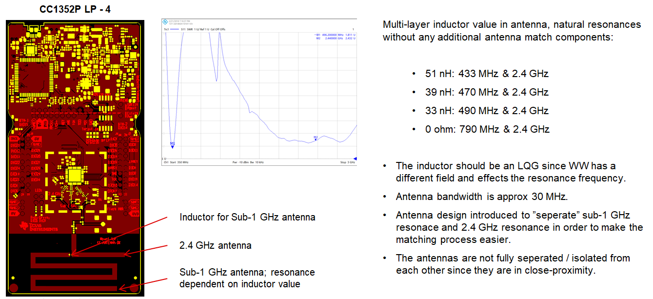
    Due to the via stitching and the total number of vias, the PCB helical antenna is very sensitive to PCB thickness variations/tolerances. For the latest CC1352P LPs at 433/490 MHz + 2.4 GHz we have used an antenna as shown below. Can you you such an antenna instead ? The resonance is set by the external inductor and this is not sensitive to PCB thickness. 

    If you do not need the 2.4 GHz operation, then the 2.4 GHz element can be removed and then the inductor value must be increased furthermore to maintain the same resonance. The exact resonance will also be dependent on the GND size.

  • At  the moment we neither have the PCB area to support this antenna nor the budget for the RF switch.

  • Hi,

    I will re-measure this antenna in the lab next week to check the resonance. 

    If the resonance is at 400 MHz, then this just needs to be re-matched with the antenna match components. 

    Regards,

        Richard

  • Hi,

    Just re-measured antenna #10 and the resonance was at 427 MHz. The measured board thickness is 1.60 mm. This antenna is very sensitive of the PCB thickness. If the PCB thickness is greater than 1.60 mm then this will move the resonance down. If we make a new version of the antenna kit, antenna #10 would be removed since it is too sensitive for PCB thickness tolerances.

    Regards,

       Richard