Other Parts Discussed in Thread: CC1310, CC1101
Hi,
I'm looking at optimising the impedance match on a custom CC1190 front-end based design and I'm looking at the data-sheet regarding the input impedances measured on a CC1190EM in LNA mode (Rx active) and in PA mode (Tx active), Figure 5 and Figure 10 respectively. These measurements are however at 915MHz whereas our radio operates at 869MHz.
What should we be looking at having as input impedance at 869MHz in LNA and in PA mode ?
Is there any reason that the match was not designed for 50 Ω on the SMA connector ?
At 915MHz in LNA mode the impedance looks more like 37+ j20 Ω, and for the PA mode it switches to 27 – j11 Ω
Our custom requirements for compatibility with as broad a range of antennas as possible ie dipoles, monopoles and various ceramic antennas makes us lean more towards a target match to 50 Ω or as close as possible …
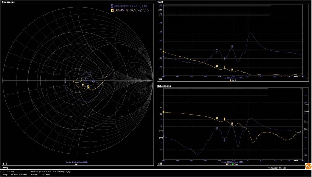
Currently we have a match in LNA mode that is close to 50 Ω, and in PA mode we measure about 26.8dBm output power which seems to suggest a reasonable match to 50Ω ...
Could you please clarify the motivation for these impedances on the CC1190EM and perhaps point us to a similar measurement for the 868MHz band if this exists for the 868MHz version of the CC1190EM ?
Looking forward to your reply.
Best Regards,
Mike