This thread has been locked.

If you have a related question, please click the "Ask a related question" button in the top right corner. The newly created question will be automatically linked to this question.

CC1310: CANT TAKE GOOD RSSI VALUE USING CC1310 WITHOUT CC1190

Part Number: CC1310
Other Parts Discussed in Thread: CC1190

Hello All,

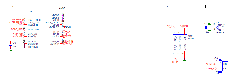
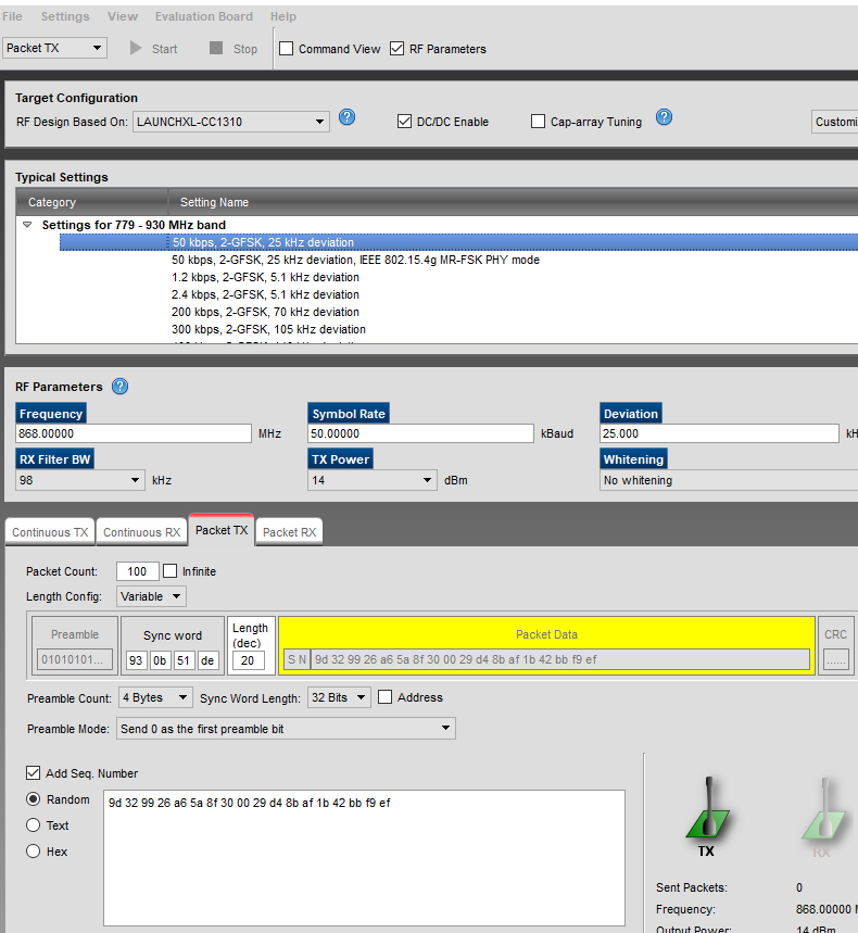
I have two custom board. I am sending data between 2 custom board. But When I want to see the rssi value of data of that I send, The value is too high. RF configurasyon is chosen LAUNCHXL-CC1310 on Device Control Panel as you see below.

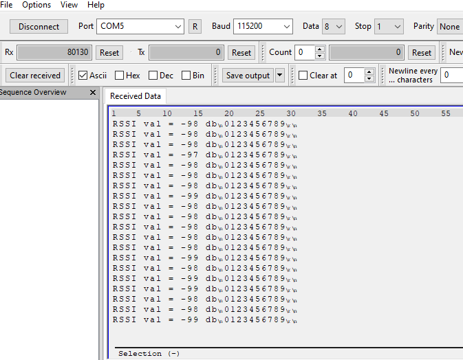
After Communication between two custom board, the rssi value that I see is below. the distance between  custom boards is only about 20 cm.

What can be done to improve rssi value? What am I missing? if you have any advice/idea to solve this problem, I would be very appricated.

Best Regards

Bekir 

  • - Use 1 m distance (or more) for RSSI testing since RSSI often saturate on shorter distance. 

    Here it looks like you get -98 dBm which indicate that the performance of your custom board is poor.  

    But: The title of this thread is confusing. Does your custom board have a CC1190 or not? Please share more details about your custom board. 

  • okay I use distance more than 1 m now. But didnt change anything yet. just more poor dbm for now.

    I have two custom board right now. The custom board which is new doesnt have cc1190. you can see the related hardware below. The other custom board which is old has CC1190. Smartrfsetting file is same for two board.so I didnt use any of HGM, PA, LNA pins. I am transmiting data by using this new custom board to the old board. I am trying to improve rssi value. but after send data using new board to the old board, I see rssi value around -(95,100)dbm.

    the major job is improve rssi value using new board. old board is just recieve the date.it will change when other new board has come.

    you can see the txfunction block and smartrfsetting.c file below

    rf_setting.c.txt
    //*********************************************************************************
    // Generated by SmartRF Studio version 2.19.0 (build#255)
    // The applied template is compatible with CC13x0 SDK version 2.10.xx.xx or newer.
    // Device: CC1310 Rev. A (2.0). 
    //
    //*********************************************************************************
    
    
    //*********************************************************************************
    // Parameter summary
    // RX Address0: 0xAA 
    // RX Address1: 0xBB 
    // RX Address Mode: No address check 
    // Frequency: 868.00000 MHz
    // Data Format: Serial mode disable 
    // Deviation: 25.000 kHz
    // Packet Length Config: Variable 
    // Max Packet Length: 128 
    // Packet Length: 20 
    // Packet Data: 255 
    // RX Filter BW: 98 kHz
    // Symbol Rate: 50.00000 kBaud
    // Sync Word Length: 32 Bits 
    // TX Power: 14 dBm (requires define CCFG_FORCE_VDDR_HH = 1 in ccfg.c, see CC13xx/CC26xx Technical Reference Manual)
    // Whitening: No whitening 
    
    #include <ti/devices/DeviceFamily.h>
    #include DeviceFamily_constructPath(driverlib/rf_mailbox.h)
    #include DeviceFamily_constructPath(driverlib/rf_common_cmd.h)
    #include DeviceFamily_constructPath(driverlib/rf_prop_cmd.h)
    #include <ti/drivers/rf/RF.h>
    #include DeviceFamily_constructPath(rf_patches/rf_patch_cpe_genfsk.h)
    #include DeviceFamily_constructPath(rf_patches/rf_patch_rfe_genfsk.h)
    #include "RF/smartrf_settings.h"
    
    // TI-RTOS RF Mode Object
    RF_Mode RF_prop =
    {
        .rfMode = RF_MODE_PROPRIETARY_SUB_1,
        .cpePatchFxn = &rf_patch_cpe_genfsk,
        .mcePatchFxn = 0,
        .rfePatchFxn = &rf_patch_rfe_genfsk
    };
    
    
    // Overrides for CMD_PROP_RADIO_DIV_SETUP
    uint32_t pOverrides[] =
    {
        // override_use_patch_prop_genfsk.xml
        // PHY: Use MCE ROM bank 4, RFE RAM patch
        MCE_RFE_OVERRIDE(0,4,0,1,0,0),
        // override_synth_prop_863_930_div5.xml
        // Synth: Set recommended RTRIM to 7
        HW_REG_OVERRIDE(0x4038,0x0037),
        // Synth: Set Fref to 4 MHz
        (uint32_t)0x000684A3,
        // Synth: Configure fine calibration setting
        HW_REG_OVERRIDE(0x4020,0x7F00),
        // Synth: Configure fine calibration setting
        HW_REG_OVERRIDE(0x4064,0x0040),
        // Synth: Configure fine calibration setting
        (uint32_t)0xB1070503,
        // Synth: Configure fine calibration setting
        (uint32_t)0x05330523,
        // Synth: Set loop bandwidth after lock to 20 kHz
        (uint32_t)0x0A480583,
        // Synth: Set loop bandwidth after lock to 20 kHz
        (uint32_t)0x7AB80603,
        // Synth: Configure VCO LDO (in ADI1, set VCOLDOCFG=0x9F to use voltage input reference)
        ADI_REG_OVERRIDE(1,4,0x9F),
        // Synth: Configure synth LDO (in ADI1, set SLDOCTL0.COMP_CAP=1)
        ADI_HALFREG_OVERRIDE(1,7,0x4,0x4),
        // Synth: Use 24 MHz XOSC as synth clock, enable extra PLL filtering
        (uint32_t)0x02010403,
        // Synth: Configure extra PLL filtering
        (uint32_t)0x00108463,
        // Synth: Increase synth programming timeout (0x04B0 RAT ticks = 300 us)
        (uint32_t)0x04B00243,
        // override_phy_rx_aaf_bw_0xd.xml
        // Rx: Set anti-aliasing filter bandwidth to 0xD (in ADI0, set IFAMPCTL3[7:4]=0xD)
        ADI_HALFREG_OVERRIDE(0,61,0xF,0xD),
        // override_phy_gfsk_rx.xml
        // Rx: Set LNA bias current trim offset to 3
        (uint32_t)0x00038883,
        // Rx: Freeze RSSI on sync found event
        HW_REG_OVERRIDE(0x6084,0x35F1),
        // override_phy_gfsk_pa_ramp_agc_reflevel_0x1a.xml
        // Tx: Configure PA ramping setting (0x41). Rx: Set AGC reference level to 0x1A.
        HW_REG_OVERRIDE(0x6088,0x411A),
        // Tx: Configure PA ramping setting
        HW_REG_OVERRIDE(0x608C,0x8213),
        // TX power override
        // Tx: Set PA trim to max (in ADI0, set PACTL0=0xF8)
        ADI_REG_OVERRIDE(0,12,0xF8),
    
        // override_phy_rx_rssi_offset_5db.xml
        // Rx: Set RSSI offset to adjust reported RSSI by +5 dB
        (uint32_t)0x000188A3,
    
        (uint32_t)0xFFFFFFFF
    };
    
    // CMD_PROP_RADIO_DIV_SETUP
    // Proprietary Mode Radio Setup Command for All Frequency Bands
    rfc_CMD_PROP_RADIO_DIV_SETUP_t RF_cmdPropRadioDivSetup =
    {
        .commandNo = 0x3807,
        .status = 0x0000,
        .pNextOp = 0, // INSERT APPLICABLE POINTER: (uint8_t*)&xxx
        .startTime = 0x00000000,
        .startTrigger.triggerType = 0x0,
        .startTrigger.bEnaCmd = 0x0,
        .startTrigger.triggerNo = 0x0,
        .startTrigger.pastTrig = 0x0,
        .condition.rule = 0x1,
        .condition.nSkip = 0x0,
        .modulation.modType = 0x1,
        .modulation.deviation = 0x64,
        .symbolRate.preScale = 0xF,
        .symbolRate.rateWord = 0x8000,
        .symbolRate.decimMode = 0x0,
        .rxBw = 0x24,
        .preamConf.nPreamBytes = 0x4,
        .preamConf.preamMode = 0x0,
        .formatConf.nSwBits = 0x20,
        .formatConf.bBitReversal = 0x0,
        .formatConf.bMsbFirst = 0x1,
        .formatConf.fecMode = 0x0,
        .formatConf.whitenMode = 0x0,
        .config.frontEndMode = 0x0,
        .config.biasMode = 0x1,
        .config.analogCfgMode = 0x0,
        .config.bNoFsPowerUp = 0x0,
        .txPower = 0xA73F,
        .pRegOverride = pOverrides,
        .centerFreq = 0x0364,
        .intFreq = 0x8000,
        .loDivider = 0x05
    };
    
    
    // CMD_FS
    // Frequency Synthesizer Programming Command
    rfc_CMD_FS_t RF_cmdFs =
    {
        .commandNo = 0x0803,
        .status = 0x0000,
        .pNextOp = 0, // INSERT APPLICABLE POINTER: (uint8_t*)&xxx
        .startTime = 0x00000000,
        .startTrigger.triggerType = 0x0,
        .startTrigger.bEnaCmd = 0x0,
        .startTrigger.triggerNo = 0x0,
        .startTrigger.pastTrig = 0x0,
        .condition.rule = 0x1,
        .condition.nSkip = 0x0,
        .frequency = 0x0364,
        .fractFreq = 0x0000,
        .synthConf.bTxMode = 0x0,
        .synthConf.refFreq = 0x0,
        .__dummy0 = 0x00,
        .__dummy1 = 0x00,
        .__dummy2 = 0x00,
        .__dummy3 = 0x0000
    };
    
    
    // CMD_PROP_TX
    // Proprietary Mode Transmit Command
    rfc_CMD_PROP_TX_t RF_cmdPropTx =
    {
        .commandNo = 0x3801,
        .status = 0x0000,
        .pNextOp = 0, // INSERT APPLICABLE POINTER: (uint8_t*)&xxx
        .startTime = 0x00000000,
        .startTrigger.triggerType = 0x0,
        .startTrigger.bEnaCmd = 0x0,
        .startTrigger.triggerNo = 0x0,
        .startTrigger.pastTrig = 0x0,
        .condition.rule = 0x1,
        .condition.nSkip = 0x0,
        .pktConf.bFsOff = 0x0,
        .pktConf.bUseCrc = 0x1,
        .pktConf.bVarLen = 0x1,
        .pktLen = 0x14,
        .syncWord = 0x930B51DE,
        .pPkt = 0 // INSERT APPLICABLE POINTER: (uint8_t*)&xxx
    };
    
    
    // CMD_PROP_RX
    // Proprietary Mode Receive Command
    rfc_CMD_PROP_RX_t RF_cmdPropRx =
    {
        .commandNo = 0x3802,
        .status = 0x0000,
        .pNextOp = 0, // INSERT APPLICABLE POINTER: (uint8_t*)&xxx
        .startTime = 0x00000000,
        .startTrigger.triggerType = 0x0,
        .startTrigger.bEnaCmd = 0x0,
        .startTrigger.triggerNo = 0x0,
        .startTrigger.pastTrig = 0x0,
        .condition.rule = 0x1,
        .condition.nSkip = 0x0,
        .pktConf.bFsOff = 0x0,
        .pktConf.bRepeatOk = 0x0,
        .pktConf.bRepeatNok = 0x0,
        .pktConf.bUseCrc = 0x1,
        .pktConf.bVarLen = 0x1,
        .pktConf.bChkAddress = 0x0,
        .pktConf.endType = 0x0,
        .pktConf.filterOp = 0x0,
        .rxConf.bAutoFlushIgnored = 0x0,
        .rxConf.bAutoFlushCrcErr = 0x0,
        .rxConf.bIncludeHdr = 0x1,
        .rxConf.bIncludeCrc = 0x0,
        .rxConf.bAppendRssi = 0x0,
        .rxConf.bAppendTimestamp = 0x0,
        .rxConf.bAppendStatus = 0x1,
        .syncWord = 0x930B51DE,
        .maxPktLen = 0x80,
        .address0 = 0xAA,
        .address1 = 0xBB,
        .endTrigger.triggerType = 0x1,
        .endTrigger.bEnaCmd = 0x0,
        .endTrigger.triggerNo = 0x0,
        .endTrigger.pastTrig = 0x0,
        .endTime = 0x00000000,
        .pQueue = 0, // INSERT APPLICABLE POINTER: (dataQueue_t*)&xxx
        .pOutput = 0 // INSERT APPLICABLE POINTER: (uint8_t*)&xxx
    };
    
    
    txfunction.c.txt
    static void txTaskFunction(UArg arg0, UArg arg1)
    {
        uint32_t time;
        RF_Params rfParams;
        RF_Params_init(&rfParams);
    
        while(1)
        {
            Semaphore_pend(semTxHandle, BIOS_WAIT_FOREVER);
    
            uint8_t j=0;
            static uint8_t veri[]="0123456789\r\n"; //12 karakter
            static uint8_t packet[PAYLOAD_LENGTH];
    
            uint8_t i;
    
            for (i = 0; i < PAYLOAD_LENGTH; i++)
            {
                //packet[i] = rand();
                packet[i] = veri[j];
                j++;
                if(j==12) //12 kARAKTER
                {
                    j=0;
                }
            }
            RF_cmdPropTx.pktLen = 12;                                                                                           
            RF_cmdPropTx.pPkt = packet;                                                                                         
            RF_cmdPropTx.startTrigger.triggerType = TRIG_ABSTIME;                                                              
            RF_cmdPropTx.startTrigger.pastTrig = 1;                                                                           
    
            if (!rfHandle){                                                                                                     
                /* Request access to the radio */
                rfHandle = RF_open(&rfObject, &RF_prop, (RF_RadioSetup*)&RF_cmdPropRadioDivSetup, &rfParams);                  
    
                /* Set the frequency */
                RF_postCmd(rfHandle, (RF_Op*)&RF_cmdFs, RF_PriorityNormal, NULL, 0);
            }
    
            /* Get current time */
            time = RF_getCurrentTime();
    
            /* Set absolute TX time to utilize automatic power management */
            time += PACKET_INTERVAL;
            RF_cmdPropTx.startTime = time;
    
            /* Send RF_Data.Raw_Buffer */
            rfTxCmd = RF_postCmd(rfHandle, (RF_Op*)&RF_cmdPropTx, RF_PriorityNormal, NULL, 0);
    
            RF_EventMask result = RF_pendCmd(rfHandle, rfTxCmd, (RF_EventCmdDone | RF_EventCmdError | RF_EventLastCmdDone |
                    RF_EventCmdAborted | RF_EventCmdCancelled | RF_EventCmdStopped));
    
            if (!(result & RF_EventLastCmdDone))
            {
                /* Error */
                while(1);
            }
    
            PIN_setOutputValue(pinHandle, Board_PIN_LED0,!PIN_getOutputValue(Board_PIN_LED0));
            memset(packet, 0, sizeof(packet)); //clear buffer
    
            Semaphore_post(semRxHandle);
        }
    }

    Best regards,

    Bekir

  • I suspect a frequency offset between the "new" and "old" boards. 

    - Have you tested a "new" board to a "new" board?

    - Have you measured the exact TX frequency they two boards operate on? 

  • I have not tested yet new board to new board. I have only one new board. I use it for transmiting.

    I have used same tx frequence 868mhz for two board.

    I also tried that for  Set RSSI offset to adjust reported RSSI by +5 dB

    (uint32_t)0x000188A3,

    and 

    .txPower = 0xA73F,

    but did not change anything too.

  • Then start by measuring the exact frequency you are transmitting on.  

  • You mean mesaure frequency using oscilloscope.to determine whether there is a sliding or not?

  • With a spectrum analyzer. 

    See also www.ti.com/.../swra603