This thread has been locked.

If you have a related question, please click the "Ask a related question" button in the top right corner. The newly created question will be automatically linked to this question.

CCS/LAUNCHXL-CC1310: ADC Sampling with accurate interval

Part Number: LAUNCHXL-CC1310

Tool/software: Code Composer Studio

Hello Dear TI Support team,

I need assistance regarding the problem I have been struggling for a long time. My plan for the future is to activate 3 ADC channels with MUX to measure three signal values. I have started from the adcBufContinuousSampling .example. Based on what I have understood so far, to jump between multiple channels, I need to use ADCBuf_RECURRENCE_MODE_ONE_SHOT (CCS).

To be more precise, I want to just get one sample from signal A, then sample B, then sample C and again repeat this sequence and I want to find out what is the maximum possible sampling frequency that I can achieve.

As a start, I have activated just one ADC channel at the moment and with the help of GPIO toggling, I am trying to find out execution sampling time. I have added my code.

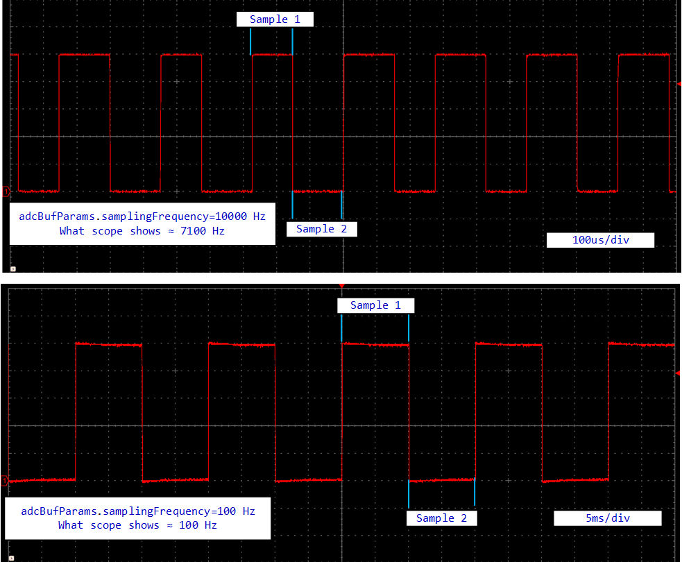
The problem I have at the moment is that for low sampling frequency (100Hz), GPIO toggle periods at the end of each sampling look equal. But once I increase the sampling frequency (10000 Hz), It cannot follow the sampling frequency anymore and I don't understand why such thing happens, Whether it comes from the GPIO timer or  ADC? Because based on datasheet, the sampling frequency should be 200Ks/S and it does not make sense to not be able to get sampling frequencies more than 10kHz.

Also, I have a question regarding the best solution to sample several ADC channels. Since I Have not found a good solution for an accurate time interval between each sample, should I use HWI for sampling?

I have added the picture of sampling intervals for two cases (100Hz and 10000Hz).

I would really appreciate if you can help me out.

Best regards,

Mori

/*
 *  ======== adcBufContinuousSampling.c ========
 */
#include <stdint.h>
#include <stdio.h>
/* For sleep() */
#include <unistd.h>

/* Driver Header files */
#include <ti/drivers/ADCBuf.h>
#include <ti/drivers/UART.h>
#include <ti/drivers/GPIO.h>
/* Example/Board Header files */
#include "Board.h"


#define ADCBUFFERSIZE    (1)

uint16_t sampleBufferOne[ADCBUFFERSIZE];
uint16_t sampleBufferTwo[ADCBUFFERSIZE]; /* * This function is called whenever an ADC buffer is full. * The content of the buffer is then converted into human-readable format and * sent to the PC via UART. */ void adcBufCallback(ADCBuf_Handle handle, ADCBuf_Conversion *conversion, void *completedADCBuffer, uint32_t completedChannel) { ADCBuf_convert(handle, conversion, 1);     GPIO_toggle(Board_GPIO_LED0); } /* * ======== mainThread ======== */ void *mainThread(void *arg0) { PIN_Handle ledPinHandle; ADCBuf_Handle adcBuf; ADCBuf_Params adcBufParams; ADCBuf_Conversion singleConversion; /* Call driver init functions */ ADCBuf_init(); GPIO_init(); /* Configure the LED pin */ GPIO_setConfig(Board_GPIO_LED0, GPIO_CFG_OUT_STD | GPIO_CFG_OUT_LOW); GPIO_setConfig(Board_GPIO_LED1, GPIO_CFG_OUT_STD | GPIO_CFG_OUT_LOW); /* Turn on user LED */ GPIO_write(Board_GPIO_LED0, Board_GPIO_LED_ON); GPIO_write(Board_GPIO_LED1, Board_GPIO_LED_ON); /* Set up an ADCBuf peripheral in ADCBuf_RECURRENCE_MODE_CONTINUOUS */ ADCBuf_Params_init(&adcBufParams); adcBufParams.callbackFxn = adcBufCallback;     adcBufParams.recurrenceMode = ADCBuf_RECURRENCE_MODE_ONE_SHOT;
    adcBufParams.returnMode = ADCBuf_RETURN_MODE_CALLBACK;
    adcBufParams.samplingFrequency = 10000; adcBuf = ADCBuf_open(Board_ADCBUF0, &adcBufParams); /* Configure the conversion struct */ singleConversion.arg = NULL; singleConversion.adcChannel = 0; singleConversion.sampleBuffer = sampleBufferOne; singleConversion.sampleBufferTwo = NULL; singleConversion.samplesRequestedCount = ADCBUFFERSIZE; if (adcBuf == NULL){ /* ADCBuf failed to open. */ while(1); } /* Start converting. */ if (ADCBuf_convert(adcBuf, &singleConversion, 1) != ADCBuf_STATUS_SUCCESS) { /* Did not start conversion process correctly. */ while(1); } /* * Go to sleep in the foreground thread forever. The ADC hardware will * perform conversions and invoke the callback function when a buffer is * full. */ while(1) { sleep(1000); } }

  • Hi Mori,

    While the sampling rate might be 10kHz in your case, the delay in the system related to turning of the DMA again, invoking all the callbacks, syncing, starting it all up again from the callback etc etc. will add into what you see.

    Also, i do not understand the usage here really, you seem to only take 1 sample / conversion. This is VERY inefficient if done with the ADCBuf driver as it is designed to fill large buffers using the DMA.

    You might want to use the "ADC Driver" only which is always single conversion and a quicker turn around compared to the ADCBuf with 1 sample.

  • Thank you for your help. It is greatly appreciated.

    I followed your suggestion and instead of ADCBuf driver, now I am using ADC Driver (as you can see in the attached code, I am using a modified version of adcsinglechannel example). But still, the sampling frequency is much lower than what I expect. As you can see in the figure, the sampling frequency is around 27kHz.

    What is my option to push this frequency higher? I wonder if this is the maximum frequency that I can achieve (I know it should be able to sample up to 200kS/s and this result is far from what I expected) or something is wrong with timers or I am making mistake somewhere in coding? If there is an alternative solution, would you please kindly help me to find examples for codes?

    Because it is really important to find out the maximum possible sampling frequency since my application heavily depends on it.

    Your help is greatly appreciated.

     *  ======== threadFxn0 ========
     *  Open an ADC instance and get a sampling result from a one-shot conversion.
     */
    void *threadFxn0(void *arg0)
    {
        ADC_Handle   adc;
        ADC_Params   params;
        int_fast16_t res;
    
        ADC_Params_init(&params);
        adc = ADC_open(Board_ADC0, &params);
    
        if (adc == NULL) {
            Display_printf(display, 0, 0, "Error initializing ADC0\n");
            while (1);
        } else {
            while (1){
        /* Blocking mode conversion */
                GPIO_write(Board_GPIO_LED0, Board_GPIO_LED_ON);
                res = ADC_convert(adc, &adcValue0);
                GPIO_write(Board_GPIO_LED0, Board_GPIO_LED_OFF);
    //    if (res == ADC_STATUS_SUCCESS) {
    //
    //        adcValue0MicroVolt = ADC_convertRawToMicroVolts(adc, adcValue0);
    //
    //    }
        }
    
        ADC_close(adc);
    
        return (NULL);
    }
    }
    /*
     *  ======== mainThread ========
     */
    void *mainThread(void *arg0)
    {
        pthread_t           thread0;
        pthread_attr_t      attrs;
        struct sched_param  priParam;
        int                 retc;
        int                 detachState;
    
        /* Call driver init functions */
        ADC_init();
        GPIO_init();
    
        /* Configure the LED pin */
        GPIO_setConfig(Board_GPIO_LED0, GPIO_CFG_OUT_STD | GPIO_CFG_OUT_LOW);
        GPIO_setConfig(Board_GPIO_LED1, GPIO_CFG_OUT_STD | GPIO_CFG_OUT_LOW);
    
    
        /* Create application threads */
        pthread_attr_init(&attrs);
    
    
        /* Create threadFxn0 thread */
        priParam.sched_priority = 1;
        pthread_attr_setschedparam(&attrs, &priParam);
    
        retc = pthread_create(&thread0, &attrs, threadFxn0, NULL);
        if (retc != 0) {
            /* pthread_create() failed */
            while (1);
        }
    
        return (NULL);
    }

  • Hi Mori,

    The 200 kbps is the HW maximum sampling rate, this is how fast it could produce samples and is not what are limiting you in this case. What you basically are doing right now is turning on and off the ADC for each sample imposes further delay between each sample. 

    I would suggest you actually use the Sensor Controller for the ADC reading instead. As this is a independent CPU on the side, it would not get impacted by what ever else TI-RTOS needs to do in the background (in case of multiple threads and interrupts).

    It should also give you quicker turn around time from sample to sample.

  • Thank you so much for your prompt reply.

    I followed your suggestion and based on the example "dev.ti.com/.../node I have created one project based on the HWI section which I believe should be the fastest possible option. However, the sampling frequency is limited to 8kHz which again is really low. Anyway, I am convinced that using MUX to sample more than one ADC input would dramatically reduce the sampling time.

    Thank you for your time.

    Best regards,

    Mori