This thread has been locked.

If you have a related question, please click the "Ask a related question" button in the top right corner. The newly created question will be automatically linked to this question.

CC1101: About RSSI of 390Mhz

Part Number: CC1101
Other Parts Discussed in Thread: TEST2

Hi, 

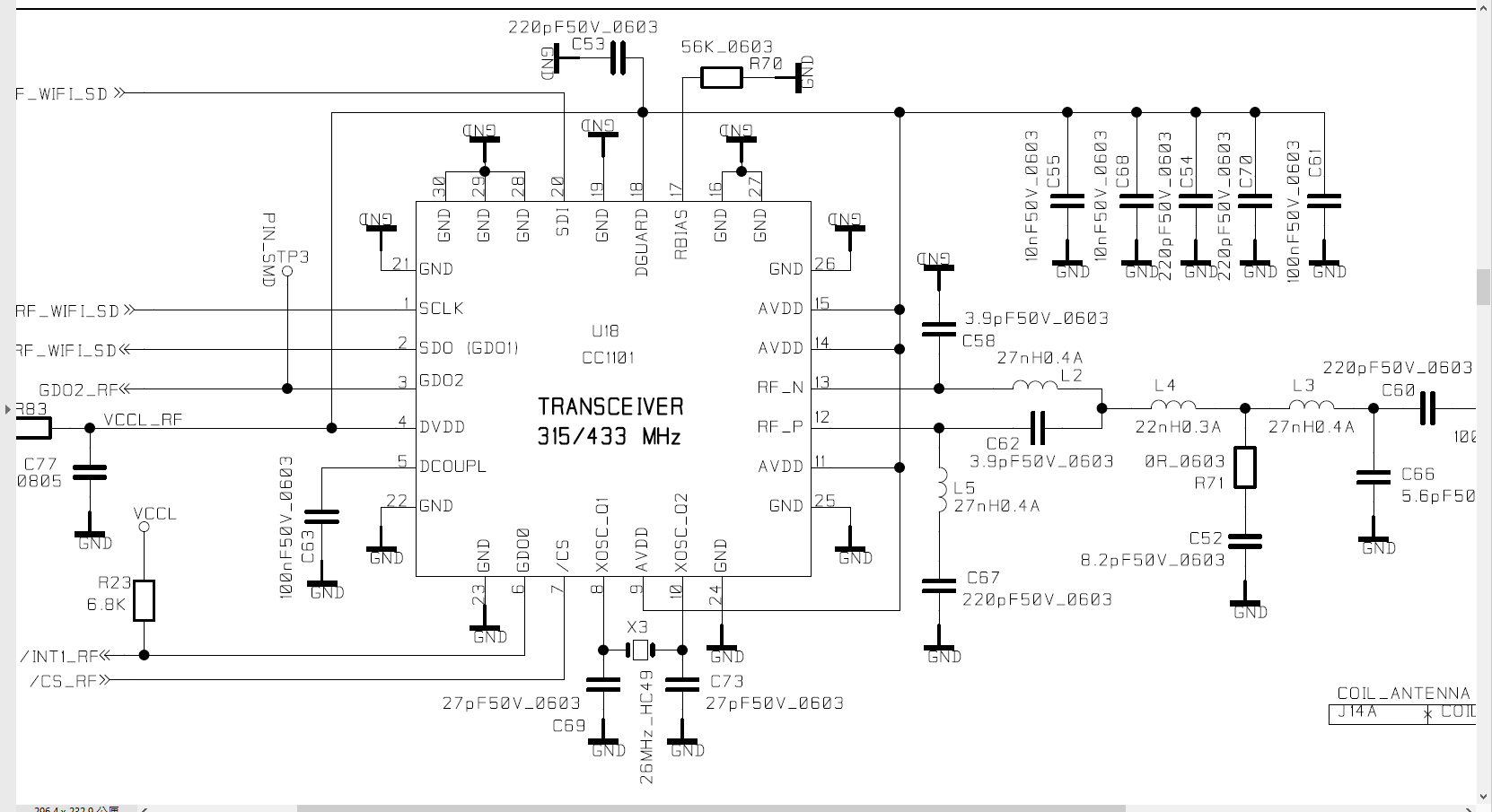
My customer is using CC1101  and they use the application and evaluation Circuit for 433 MHz by following the P25/P26 of datasheet.

They plan to get the RSSI of 315MHZ, 433MHZ and 390Mhz.

They found the design can get 315MHz and 433 Mhz, but it can not get the RSSI of 390Mhz.

Please help to check if there is possible to make them can also get the RSSI of 390Mhz.

If it is possible, please help to provide suggestion.

Thanks.

  • A bit unclear how they actually test this.

    Are they able to send a CW on the frequencies in question?

    Which frequency is used for the xtal?

    Note: They should always base their boards on the reference design, not the simplified drawing from the datasheet. 

  • Hi TER, 

    Customer reply that the XTAL is 26MHz.

    Besides, what is CW ?

  • CW - Continuous wave. How to send a CW is covered in multiple posts on E2E. See as one example https://e2e.ti.com/support/wireless-connectivity/other-wireless/f/667/t/157309

  • Hi, 

    Customer have 2 sets of PCB board, 1st board transmit 390MHz through CC1101 continuously,

    and the 2nd board try to receive 390MHz through CC1101.

  • Have the measured that the board is actually sending @390 MHz?

  • Hi, 

    Two PCBA are used. PCBA-1 for Tx and PCBA-2 for Rx.

    The following are the test results:

    Test Freq. Test Result Note
    433 Mhz Pass Can Get RSSI
    315 Mhz Pass Can Get RSSI
    360 MHz Pass Can Get RSSI
    370 MHz Fail Can not Get RSSI
    390 MHz Fail Can not Get RSSI

    Thanks.

  • The table does not give me any new information. 

    Is it just the RSSI measurements that "fail" or other tests? What is the definition of "fail" in this context? 

  • Dear TER,

        I am the customer of Mike, we sell handheld devices that using CC1101 chip in out PCB.

    Our device is designed to detect signal strength of car remote control (like iKey, 315MHz in the US, 433MHz in the Europe)

    Now I have a mass production device could receive RSSI perfectly in 315MHz and 433MHz,

    the circuit design completely followed application note in 433 column in datasheet.

    And this month our customer wants to detect another frequency, that is 390MHz. 

    Originally I think it could be easy but when I added a feature that receiving 390MHz RSSI, I can not see signal strength changing.

    There are two experiments:

    1. press 390MHz remote control and receive it with our device, the RSSI value did not change, keep the same like background noise.

    I think it is a continuous wave.

    2. try to transmit 390MHz through our device (the mass production device) and receive signal with another device (also the same device as mass production one), I can not see RSSI value to change.

    Then I try to let our device to transmit 380MHz, receiving side still can not see RSSI value to change.

    But when I try to let our device to transmit 370MHz, I am able to see RSSI value increased 6dBm

    And then I try to let our device to transmit 360MHz, I am able to see RSSI value increased 25dBm

    And then I tried from 315MHz to 360MHz the RSSI value will increase 25~35 dBm, 

    I also tested 400MHz and 410MHz, there is no RSSI value change in these 2 frequencies.

    But when I try to let our device to transmit 420MHz, I am able to see RSSI value increased 35dBm in my receiving device.

    These are experiments I made, using same device to transmit different frequency through CC1101 will have different result.

    So my question is that, is this experiment result reasonable?

    If yes, my second question is that in what way can I receive 390MHz signal strength through CC1101? different LC settings? or merely different register settings?

    Thank you.

  • I see two potential issues:

    - Register settings. What is the delta in SW when you test on the different frequencies? 

    - Hardware. Even hardware that is designed for a given frequency should see a change in RSSI for other frequencies. Is it possible to share  the schematic? Send me a friend request if  you don't want to share it in public.  

  • Register settings: what does delta means? I set AGCCTRL1 = 0x00, AGCCTRL2 = 0x07, MDMCFG4 = 0xF6, is this information enough?

    Schematic is like below, rightmost connect to antenna directly

  • The schematic looks to be inline with the 433 MHz ref design (https://www.ti.com/tool/CC1101EM433_REFDES) Note that it's recommended to use a different BOM for 315 MHz but that should not impact the failure to get RSSI.

    For registers/ software: 

    - I would like to review the full register list to get an overview, I would need two register sets, one for a frequency you read out the correct RSSI and one for 390 MHz where you see issues. What do you differently.

    - Is it possible to share the part of the code that contains the RSSI readout? 

    Are you able to apply a CW from a signal generator and increase the power from - 100 dBm to -20 dBm and read out the RSSI for selected steps.

  • first answer register settings, other will be posted later

    if the register is not in my list below, that means it is power on reset default value

    0x06, // FSCTRL1 Frequency synthesizer control.
    0x00, // FSCTRL0 Frequency synthesizer control.
    0x0E, // FREQ2 Frequency control word, high byte. // this frequency will be overwritten in case of RKE test
    0xFF, // FREQ1 Frequency control word, middle byte.
    0xF9, // FREQ0 Frequency control word, low byte.
    0xF6, // MDMCFG4 Modem configuration.
    0x83, // MDMCFG3 Modem configuration.
    0x3B, // MDMCFG2 Modem configuration. //Enabled Manchester or Not, bigger difference in RSSI reading
    0x22, // MDMCFG1 Modem configuration.
    0xF8, // MDMCFG0 Modem configuration.
    0x00, // CHANNR Channel number.
    0x15, // DEVIATN Modem deviation setting (when FSK modulation is enabled).
    0x56, // FREND1 Front end RX configuration.
    0x11, // FREND0 Front end TX configuration.
    0x18, // MCSM0 Main Radio Control State Machine configuration.
    0x16, // FOCCFG Frequency Offset Compensation Configuration.
    0x6C, // BSCFG Bit synchronization Configuration.
    0x07, // AGCCTRL2 AGC control.
    0x00, // AGCCTRL1 AGC control.
    0x91, // AGCCTRL0 AGC control.
    0xE9, // FSCAL3 Frequency synthesizer calibration.
    0x2A, // FSCAL2 Frequency synthesizer calibration.
    0x00, // FSCAL1 Frequency synthesizer calibration.
    0x1F, // FSCAL0 Frequency synthesizer calibration.
    0x59, // FSTEST Frequency synthesizer calibration.
    0x81, // TEST2 Various test settings.
    0x35, // TEST1 Various test settings.
    0x09, // TEST0 Various test settings.
    0x47, // FIFOTHR RXFIFO and TXFIFO thresholds.
    0x0D, // IOCFG2 GDO2 output pin configuration. //related with HW IO usage, do not change
    0x06, // IOCFG0 High Z no interrupt //related with HW IO usage do not change
    0x04, // PKTCTRL1 Packet automation control.
    0x05, // PKTCTRL0 Packet automation control.
    0x00, // ADDR Device address.
    0xFF // PKTLEN Packet length.

  • The difference between 390MHz register setting and 433MHz register settings is only FREQ2, FREQ1, FREQ0. I did not change any other register value while RSSI strength test.

  • Answer your 2nd and 3rd question

    I have no signal generator, I only have iKey, and RSSI value becomes lower (10dBm or 15dBm) while iKey is 80cm from receiver, value becomes higher

    (30dBm up) while iKey is very close to receiver.

    And RSSI readout code is like below

    void ReadRssi(void)
    {
    short sTmp;
    unsigned char cRssi;

    sTmp = -1;
    rRfRssi.sVal = -1;

    CC11xxReadBurstReg(CC11xx_RSSI,(UCHAR *)&cRssi,1);
    rRfRssi.sVal = (short)cRssi;

    //convert to dbm value
    if(cRssi >= 128)
    {
    //rRfRssi.sVal = (cRssi-256)/2 -74;
    rRfRssi.sVal = ((short)(cRssi>>1)) - 128 -74; //modified by wolfgang
    }
    else
    {
    rRfRssi.sVal = ((short)(cRssi/2)) -74;
    }

    }

  • I have limited bandwidth for hardware testing:

    Would you be able to do a test with a slightly different xtal frequency? 390 MHz is a integer multiple of 26 MHz.

  • Do you mean I test 390.1MHz and 390.2MHz ?

  • That is one option, the other option is to use slightly higher xtal frequency, 26.1 MHz or similar.