This thread has been locked.

If you have a related question, please click the "Ask a related question" button in the top right corner. The newly created question will be automatically linked to this question.

BP-CC3301: LP-EM_CC1354P10 with BP-CC3301

Part Number: BP-CC3301
Other Parts Discussed in Thread: LP-XDS110ET, CC1354P10, CC3301, BP-CC33-BBB-ADAPT, LP-EM-CC1354P10

Tool/software:

Dear TI Sirs:

  I use the cc33xx-mcu-plugin-ble-0.6 from MySecure.

  I have board LP-EM-CC1354P10-1 with BP-CC3301.

  However due to I have no LP-XDS110ET but only XDS110, I contact the local support and confirm the XDS110 is also working as long as not to use the energy trace feature.

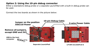
  I connect the board as describe inside the document:

XDS110 PWR3V3 ==> LP-EM_CC1354P10 ==> BP-CC3301

After I connect the board as described inside "CC13xx/26xx Host: Getting Started Guide" section "Setup - CC13xx/CC26xx and CC33xx"

In the above case, I always get "SPI not responsive" from console. Latter I measure the power on BP-CC3301, I got 3V2 on pin 3V3 and 0.9V on pin 5V, it seems the power is not correct and not enough, so I decide to measure the same board in BeagleBone Black, which when startup and CC3301 is running, the power is 3V4 on pin 3V3 and 5V1 on pin 5V.

After this, I suppose the power is something weird  in my setup, so I change to power from BBB. And the BBB is not running both eMMC is empty and SD is not attached.

At this case,

BBB PWR 3V3 ==> BP-CC3301  & LP-EM_CC1354P10

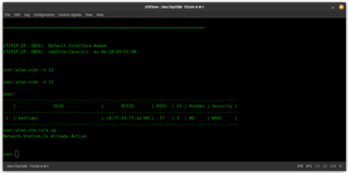
When running in the above case, I see following:

And

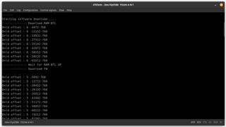
However, it failed on the end:

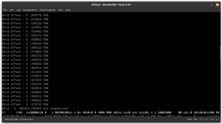
And I try to attach the XDS110 to see what had happened above. However at this time, I always see the "SPI not responsive" as long as I run in debugger.

I know inside the document TI uses LP-XDS110ET to power to do everything for the example,

my questions are:

1. Have TI ever try to use a XDS110? If yes, at this case, I do you connect the board and power it?

2. What is the PG version of BP-CC3301 you used on the example? PG2 or PG1?

Regrds,

/ckhsu

  • Hello,

    I think there might be some confusion here on the setup. 

    What revision of BP-CC3301 do you have? In the top right hand corner of the board it should say Rev E2/E3/A. If it doesn't say anything then that means Rev E1. 

    I can help clear up some things about the setups you tried.

    1. LP-XDS110ET - this board and the XDS110 debug probe have the same functionality this is true. However using the LP-XDS110ET is more recommended because you can connect power to the LP-EM_CC1354P10 without any extra wires. I am not sure how you connected power 3v3 to the LP-EM_CC1354P10 from the XDS110. maybe you can send a schematic or picture. The power that the LP-XDS110ET provides to the LP-EM_CC1354P10 is 5V. 

    2. Power to the BP-CC3301 - there is a 3V3 pin on the BP-CC3301 but this does not provide power to the CC3301 IC. If you want to power the BP-CC3301 you must power the 5V pin. This is why you don't see any voltage on the 5V pin when connecting power to the 3V3 pin, and most likely why the first setup you tried didn't work. When connecting the BBB to the BP-CC3301 with the BP-CC33-BBB-ADAPT the power that is sourced from the BBB to the BP-CC3301 is through the 5V pin, that's why that setup works for you in terms of power.

    3. BBB - although this will power the BP-CC3301 correctly, there might be some signal contentions with pins connected to the BBB and LP-EM_CC1354P10 at the same time. You should follow the setup as written in the docs folder of the cc33xx-mcu-plugin-ble-0.6. If you are having trouble send me a picture of your setup.

    Long story short, I think the issues you are seeing are because of the setup, please follow the instructions accordingly.

    Regards,

    Jonathan 

  • Hello Jonathan:

      Thank you for the reply.

      My BP-CC3301 is Rev E3 with PG2 CC3301, if any other version of the board should be used like Rev E1, please let me know.

      In fact, I also try the 5V power from LP-EM_CC1354P10 before I post, and the situation is something more weird that the console always show SPI not responsive. The power source from XDS-110 is from the expansion header.

    The power of 3V3 is from pin 27, if 5V then it is from pin 28 and GND from pin 25 as describe in XDS110 Debug Probe User's Guide(sprui94) to LP-EM_CC1354P10 and to BP-CC3301.

      And you can see in LP-EM-CC1354P10-1 Quick Start Guide(spruiz8) or LP-EM-CC1354P10-6 Quick Start Guide(spruiz9), when using Option 2: Using the 10-pin debug connector

    The manual only connect Power 3V3 from XDS-110, that's the reason we connect 2 wire power 3V3 from XDS-110 pins.

      Since the power from LP-XDS110ET is 5V from the above response, I will try this 5V case of XDS110 from the connector to see the result and response here accordingly.

    Regards,

    /ckhsu

  • Hi,

    BP-CC3301 Rev E3 with PG2 CC3301 should work.

    Let me know what results you get when trying to connect the 5V from the XDS110. There may still be problem with current if you connect the XDS110 only to your computer, normally the USB ports on your computer don't give enough current for both the .LP-EM-CC1354P10 and BP-CC3301. 

    On the BP-CC3301 there is a micro usb port which can be used for power, you can try to connect this to a power brick to the wall or to your computer for extra power. 

    In addition I would try first booting up the LP-EM-CC1354P10 without the BP-CC3301 connected just to see if this works okay. Lets see if the problem is with the LP-EM-CC1354P10 and XDS110 connection or with the connection of all 3 boards together. 

    Let me know.

    Thanks,

    Jonathan

  • Hello Jonathan:

      Thank you for the reply.

      I also just make it working in my site. By using XDS110 and extra power.

      Thank you for the support.

    Regards,

    /ckhsu