CC3230SF: Connect XDS110

Part Number: CC3230SF
Other Parts Discussed in Thread: CC3230S, UNIFLASH

Tool/software:

Hi,

My customer has developed their own board with CC3230SF12RGKR.

They want to write software via XDS110, but can’t do that now. They’re not sure if it can be connected correctly to CC3230.


When XDS is connected to PC, “NOserial” is displayed. Is the XDS110 connected correctly ?


They want to confirm the JTAG connection.


There is the following description in the XDS Debug Probe User's Guide. 

2.3 Debug Interface

        The XDS110 probe supports a debug connection interface through the standard CTI-20 connector (see Section 2.3.1). The supported debug features include:

  • 5-pin 1149.1 JTAG connection (including TRSTn)


Does this 5-pin mean Pin 1, 2, 3, 7 and 11 of CTI-20 ?


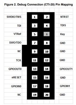
Is the connection below correct ?

「CTI-20」 - 「CC3230S」
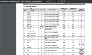
 TMS      -  Pin20

 TCK       -  Pin19

    TDO      -  Pin17  

 TDI        -  Pin16

 RESET      -  Pin32


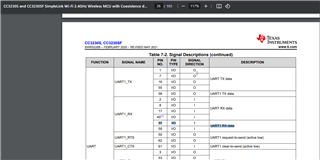
TX and RX of UART are input? or output? from UART point of view.


「XDS110」 - 「CC3230S」

 UARTRX  -  Pin57

 UARTTX  -  Pin55


 Thanks and regards,

Hideaki 

  • Hi,

    Could I have any response ?

    Thanks and regards,

    Hideaki

  • Hi apologies for the delay.

    The mentioned connections seem correct. They can refer to the datasheet at https://www.ti.com/lit/SWRS226 for information on the device pins.

    Page 11 shows TMS, TCK, TDO, TDI, and nRESET pins:


    Page 26 shows that the RX and TX (pin 57, and 55) expect input and output signals (point of view from the CC32xx device). As such RX is an input for the CC32xx, and TX will output from the CC32xx

    Would recommend they also check out our Launchpad (https://www.ti.com/tool/LAUNCHXL-CC3235S), and the documentation for it.

    Lastly I would recommend they refer to our design guidelines for the CC3235 and apply to get a HW design review by going to https://www.ti.com/tool/SIMPLELINK-WIFI-DESIGN-REVIEWS.

    BR,

    JMT

  • Hi,

    Just a quick comment. I think that connection is NOT 100% correct.

    • It is missing connection for target detect VTREF pin
    • It is missing GND conenction
    • I think (I am not 100% sure right now) but Uniflash (image creator) does not control reset pin at XDS110. It control one of  GPIOPIN at XDS110.

    Jan

  • Hi JMT and Jan,


    Thank you for your responses and sorry for my delayed response. Let me confirm a little more.

    We want to confirm the following status.

    Since XDS110 USB Debug Probe is shown in the "Connection", XDS110 has been able to be connected correctly ?

    What's the Serial Number ? Device serial # ? Baord serial # ? or JTAG serial # ?

    It is missing connection for target detect VTREF pin

    They think this pin is used for verifying whether power inputs to the target (CC3230S) correctly.

    They confirmed the power inputs to the target correctly and connect VTREF pin to the power on the target. After that they tried again to flash, but no change in the situation.

    It is missing GND conenction

    Pin 20 is connected to GND.

    All GND pins (Pin 8, 10, 12 and 20) must be connected ?

    I think (I am not 100% sure right now) but Uniflash (image creator) does not control reset pin at XDS110. It control one of  GPIOPIN at XDS110.

    Do you mean that RESET is needed between PC (UniFlash) and XDS110?

    Could you tell them concretely how to create RESET pinby GPIOpin of XDS110 ?

    Thanks and regards,
    Hideaki

  • Hi Hideaki,

    • Serial number means serial number of XDS110 debugger.
    • It is enough to be connected to one of GND pins.
    • For proper function of Uniflash, it needs to be controlled reset pin of CC32xx. At CC32xx LaunchPad this is done via PA6 pin of XDS110 (XDS110 chip). I think RESET pin at CTI-20 connector is not right one. I think you can try to probe pins when you try to connect via Uniflash. Maybe right pin is one of GPIO pins at AUX connector. But I don't know exact answer.

    Jan