This thread has been locked.

If you have a related question, please click the "Ask a related question" button in the top right corner. The newly created question will be automatically linked to this question.

LAUNCHXL-CC3235S: SysConfig pins settings unexpectedly reset after rebuild project

Part Number: LAUNCHXL-CC3235S
Other Parts Discussed in Thread: IWR6843, CC3235S, SYSCONFIG, OPA4342, TIDA-010022, MMWAVEICBOOST

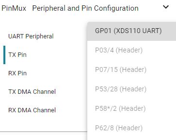
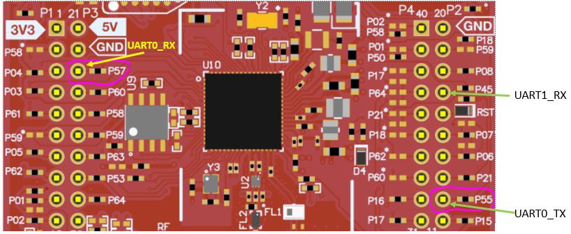
My application is to send data from IWR6843 to CC3235 via UART. I used both UART0 & UART1 on CC3235S. Here's my settings for UART pins

UART1

static const UARTCC32XX_HWAttrsV1 uartCC32XXHWAttrs0 = {
    .baseAddr           = UART1_BASE,
    .intNum             = INT_UART1,
    .intPriority        = (~0),
    .flowControl        = UARTCC32XX_FLOWCTRL_NONE,
    .ringBufPtr         = uartCC32XXRingBuffer0,
    .ringBufSize        = sizeof(uartCC32XXRingBuffer0),
    .rxPin              = UARTCC32XX_PIN_02_UART1_RX,	
    .txPin              = UARTCC32XX_PIN_UNASSIGNED,	
    .ctsPin             = UARTCC32XX_PIN_UNASSIGNED,
    .rtsPin             = UARTCC32XX_PIN_UNASSIGNED,
    .errorFxn           = NULL
  };

UART0

static const UART2CC32XX_HWAttrs uart2CC32XXHWAttrs0 = {
    .baseAddr           = UART0_BASE,
    .intNum             = INT_UART0,
    .intPriority        = (~0),
    .flowControl        = UART2CC32XX_FLOWCTRL_NONE,
    .rxDmaChannel       = UDMA_CH8_UARTA0_RX,
    .txDmaChannel       = UDMA_CH9_UARTA0_TX,
    .rxPin              = UART2CC32XX_PIN_04_UART0_RX,	//UART2CC32XX_PIN_45_UART0_RX,
    .txPin              = UART2CC32XX_PIN_03_UART0_TX,	//UART2CC32XX_PIN_62_UART0_TX,
    .ctsPin             = UART2CC32XX_PIN_UNASSIGNED,
    .rtsPin             = UART2CC32XX_PIN_UNASSIGNED,
  };

But after each time I rebuild project (network_terminal), I see the SysConfig in Debug folder of project in the workspace reset to default pins settings (only UART0 at pin 57, 55) even though I set UART0 to pin 3, 4 and UART1 to pin 2 in ti_drivers_config.c before I rebuilt project on CCS. It's weird. It caused my program can't transfer data via the UART pins I set on SysConfig before. Please tell me how to solve this issue.

  • Hi,

    You need to set your UART pin configuration inside Sysconfig GUI.

    Jan

  • Hi Jan,

    Can you explain more clearly? I only see SysConfig on dev.ti.com.

    Besides, after I imported project on CCS, it automatically created project folder in workspace path, including  ti_drivers_config.c and  ti_drivers_config.h. Then I only need to modify ti_drivers_config.c as the pins settings according to schematics of CC3235. Where's the SysConfig GUI located and how to set it? It'd be great if you can show illustration photos the steps. Thanks.

  • Hi Hector,

    See the SysConfig Tool Basics lab: http://dev.ti.com/tirex/explore/node?node=AO3dBAhu05HBWXd.SPxt0g__fc2e6sr__LATEST

    Best regards,

    Sarah

  • Hi Jan,

    I checked common.sysconfig in CCS. I can only choose UART0 RX/TX as XDS110 UART. But XDS110 UART is J9 jumper set to top side. I also need to use UART1 with J9 jumper set to bottom side. I think UART0 TX/RX should be set to pin 3,4 on boosterpack header, but those pins are in grey color, so I can't choose them. Is it ok to choose UART0 at XDS110 pins? XDS110 is to route UART to COM port, not boosterpack header, right? How can I set Sysconfig for both UART1 & UART0 in this case?

  • Hi,

    Please wait for answer from Sarah regarding Sysconfig setup.

    How are pins from CC32xx QFN connected to booster pack at XDS-110 UART you find at schematic. My best advice is to look into schematic and figure out how CC3235S Launchpad is connected. Without this understanding you will not be able move forward.

    Jan

  • Jan,

    Last time I described to you my understanding of schematics and you confirmed that it's correct. This issue is about SysConfig doesn't let me choose pins settings as I want, it doesn't mean I don't understand schematics.

    Please tell me which pin on boosterpack header CC3235S I need to connect in case UART0 pins settings on SysConfig are fixed at pin 57 for RX, 55 for TX

    .rxPin = UARTCC32XXDMA_PIN_57_UART0_RX,
    .txPin = UARTCC32XXDMA_PIN_55_UART0_TX,

    As I see, only pin 55 on SysConfig can connect to GPIO_01 (pin 18 on boosterpack header P2), but pin 57 set on SysConfig doesn't has any connection to boosterpack header.

    Anyways, I didn't choose "use DMA" for UART0 on SysConfig, but rxPin, txPin of UART0 still has DMA. Why is it?

  • Hi,

    if you say this "I also need to use UART1 with J9 jumper set to bottom side."  I am not a pretty sure that you understood all things about hardware of LaunchPad properly. Center pin of J9 is connected to pin 55 of QFN (alias GPIO01). According setup of J9 you connect this QFN pin to XDS-110 UART or to booster pack connector. Pin 55 of CC3235S QFN can be set to following functions (from datasheet):

    • GPIO1
    • UART0_TX
    • pCLK
    • UART1_TX
    • GT_CCP01

    Once you select one function you cannot use additional function of pin (if you select UART0_TX you cannot select UART1_TX at same time). If pin is is already used, Sysconfig does not allow to select function/pin again. This prevent you for a wrong device configuration. I don't see any reason why using of DMA with UART will cause any issue.

    Please wait for additional comment related to Sysconfig setup from Sarah.

    Jan

  • Jan,

    You're enthusiastic. About pins settings, I didn't make any pin conflict. There's no function is set at pin 3, 4. But I can't choose pin 3, 4 for UART0.

    Anyways, if I can't change settings on SysConfig and can only use pin 55, 57 for UART0 TX/RX functions, the wiring should be like below, right? (UART0_TX wiring at 3rd pin on P3, UART0_RX wiring at 9th pin on P2) and J9 jumper set to bottom side.

  • Hi,

    Yes, statement about location of pins 55, 57 is correct, but you need to have properly set jumpers J9 and J10. Do not forgot that RX pin is connected via buffer with OPA4342 and this may/may not affect function of your UART.

    Jan

  • Hi,

    I forgot to ask. If UART1_RX is set .rxPin = UART2CC32XX_PIN_45_UART1_RX,

    So the wiring for UART1_RX is at 4th pin from top side on P2, right?

    About J9 jumper, I think it's very clear, so it's impossible to set it wrong. Just need to set as below. Anyways, I don't see J10. Where is it?

    Can you send me document related to buffer with OPA4342? I'm not sure how it can affect UART function. How to make it not affect?

  • Hi,

    I forgot to ask. If UART1_RX is set .rxPin = UART2CC32XX_PIN_45_UART1_RX, So the wiring for UART1_RX is at 4th pin from top side on P2, right?

    For CC3235S device is this correct.

    About J9 jumper, I think it's very clear, so it's impossible to set it wrong. Just need to set as below. Anyways, I don't see J10. Where is it?

    J10 is a RX jumper. Before asking such question please look to schematic in the future.

    Can you send me document related to buffer with OPA4342? I'm not sure how it can affect UART function. How to make it not affect?

    Generally you should not expect issue with your UART RX via this pin. Here is described how voltage follower (buffer) does work.

    Jan

  • Part Number: LAUNCHXL-CC3235S

    I referred to TIDA-010022. The pins settings of UART0, UART1 and wiring for CC3235S is as follows:

    UART0 pins settings (send Configuration from CC3235 to IWR6843)

    .rxPin              = UART2CC32XX_PIN_57_UART0_RX,  
    .txPin              = UART2CC32XX_PIN_55_UART0_TX,

    UART1 pins settings (to receive radar data from MSS_LOGGER pin of IWR6843 EVM)
    .rxPin              = UARTCC32XX_PIN_02_UART1_RX,  
    .txPin              = UARTCC32XX_PIN_UNASSIGNED,   

    Wiring CC3235S & MMWAVEICBOOST

    CC3235S(boosterpack header)        IWR6843 MMWAVEICBOOST

      GND                                                    GND

      P57                                                     TX (pin 5 on J5)

      P55                                                     RX (pin 7 on J5)

      P45                                                     MSS_LOGGER (pin 9 on J6)

    wiring position on Boosterpack header CC3235S

    I also set J9 jumper RX/TX to bottom side as the yellow region as below

    I powered on CC3235S by USB port. 

    In theory, CC3235S can send Cfg to IWR6843 via P55, P57 connected to TX,RX on MMWAVEICBOOST. But after I powered on both modules and use Teraterm to check data, both modules don't have any data. On CC3235S, I have 

    UART_write(mmwaveUartHandle, &CommandList[command_index][byte_index], 1);

    Where, CommandList[] is array of parameters to send to IWR6843.

    const char *CommandList[] = {"dfeDataOutputMode 1\r",
                        "channelCfg 15 5 0\r",
                        "adcCfg 2 1\r",
                        "adcbufCfg 0 1 1 1\r",
                        "profileCfg 0 60.6 30 10 62 0 0 53 1 128 2500 0 0 30\r",
                        "chirpCfg 0 0 0 0 0 0 0 1\r",
                        "chirpCfg 1 1 0 0 0 0 0 4\r",
                        "frameCfg 0 1 128 0 50 1 0\r",
                        "lowPower 0 1\r",
                        "guiMonitor 1 1 0 0\r",
                        "cfarCfg 6 4 4 4 4 16 16 4 4 50 62 0\r",
                        "doaCfg 600 1875 30 1 1 0\r",
                        "SceneryParam -6 6 0.5 6\r",
                        "GatingParam 4 3 2 0\r",
                        "StateParam 10 5 100 100 5\r",
                        "AllocationParam 250 250 0.25 10 1 2\r",
                        "AccelerationParam 1 1 1\r",
                        "PointCloudEn 0\r",
                        "trackingCfg 1 2 250 20 52 82 50 90\r",
                        "sensorStart\r"
    };

    I flashed bin file of xwr68xx demo code for IWR6843. Not sure whether the Cfg above is not suitable for xwr68xx demo code.

    I don't know why this code can't write Cfg to IWR6843. 

    Even though I tried to send Cfg from PC directly to IWR6843, then CC3235S didn't receive any data from MSS_LOGGER pin.

    Someone may think that I set J9 jumper to short 2 pins bottom side (route UART to boosterpack header), but I connected all 3 pins of RX on J9 jumper. So normally it can get data from Mss_logger & check data via UART COM port by Teraterm at the same time.

    Please tell me how to transfer data successfully between these 2 modules via UART.

  • Hi Sarah,

    Why can't I set pin 3,4 for UART0? I can only set XDS110 for UART0, corresponds P55, P57. Even though I haven't set other pins for any function. 

    Currently, I connected UART0 to P55, P57; UART1_RX to P45 on boosterpack header and I use simple code as uartecho in SDK for UART_read(). But I haven't received data on CC3235S.

  • Hi Jan,

    Can you send me code that successfully transfer data between CC32XX & external device via UART or SPI? In theory, we only need to connect pins between modules and do UART_write(), UART_read(). You already confirmed my wiring is correct. About UART code, I used uartecho in SDK to read data from radar IWR6843. I also connected 3 pins of J9 RX jumper. But I don't see any data on Teraterm.

    A weird thing I see is: even when I set J9,J10 jumper to bottom side, then I connect CC3235 to PC via usb port, COM port still shows in Device Manager of Windows. As I know, set jumper to bottom side will disable COM port, why it's still appearing?

  • Hi,

    At CC32xx SDK are examples "uartecho" and "spimaster" and this examples demonstrates how to us UART and SPI with TI Drivers. You need to change code of examples according your needs of course. I am not able to say what you can have wrong. Maybe you can use use logical analyser and look to your UART data directly.

    Jumpers J9, J10 disconnects only RX, TX line. It does not affect function of virtual COM port via XDS-110 debugger.

    Jan

  • Hi,

    1. mmwave_sensor.c code in TIDA-010022 design should be ok to receive data from IWR6843 because TI tested it before. I checked UART function of CC1352 is same as CC3235S, so we can use it directly. Of course, I removed some parts of 15.4 stack in mmwave_sensor.c code, since I don't need it now.

    When I build network_terminal project with mmwave_sensor.c integrated, it showed error unresolved symbol mmwaveSensor and Util_buildUint32, even though I added util.h and necessary include file from TIDA-010022 into network_terminal project folder. Do you think what caused this error?


    2. What's the difference between CC3235S_LAUNCHXL.c & ti_drivers_config.c? I see they are both pins settings. So I don't put CC3235S_LAUNCHXL.c in my project, only use ti_drivers_config.c.

    When to use CC3235S_LAUNCHXL.c code?

  • Hi,

    1. I am not familiar with that code inside mmwave_sensor.c.

    2. File ti_drivers_config.c is TI drivers configuration generated by Sysconfig during build of code. File is a CC3235S_LAUNCHXL.c TI drivers configuration as well. In case you are using Sysconfig file CC3235S_LAUNCHXL.c will not be inside your project.

    This is a my last answer at this thread. Unfortunately I am not able/want spend such quantity of time with answering question which can easily resolve by other resources (by search at e2e forum, from schematic, SimpleLink academy, etc.). Other your question will be answered by TI support.

    Jan

  • Hi Hector,

    The overview in the SysConfig Tool Basics lab provided explains the legacy CC3235S_LAUNCHXL.c code.

    Best regards,

    Sarah

  • Hi Sarah,

    I knew this thing before. I just want you to confirm whether my wiring for UART0, UART1 is correct? I posted wiring position in the photo last week.

  • Hi Hector,

    Yes, the pins you are using on your LaunchPad look correct.

    Best regards,

    Sarah

  • Hi Sarah,

    I set s UART ports: UART0 uses hardware XDS110 (pins P55, P57), UART1 uses boosterpack header pin P45.

    When I only initialize UART0, I can send command to CC3235 via Teraterm to begin AP and WLAN connection normally. But after I initialized UART0 & UART1 and do some UART_control() or UART_read() with UART1, I can't type command on Teraterm that was connecting to PC via micro USB port anymore.

    So I wanna double-check: Does it mean I can only set UART0 & UART1 using boosterpack header pins to control both UART ports at the same time (maybe not set UART0 at hardware XDS110 pins but set it at P03, P04)? 

  • Hi Hector,

    You already posted this. Use your current thread: https://e2e.ti.com/support/wireless-connectivity/wifi/f/968/t/910142

    Best regards,

    Sarah

  • Hi Sarah,

    Because nobody replied my question in that thread, so I forgot it. Please help me handle the issue in that thread.