This thread has been locked.

If you have a related question, please click the "Ask a related question" button in the top right corner. The newly created question will be automatically linked to this question.

CC3235S: Uniflash error when flashing to a CC3235S based hardware

Part Number: CC3235S
Other Parts Discussed in Thread: CC3235MODAS, UNIFLASH

Hello,

I am trying to bring-up CC3235S (actually CC3235MODAS) on a custom board. I am using TI MCU for the first time. So far I was not able to load any code to the CC3235S. I tried to load code using XDS110 but it fails to connect to the MCU (I tried SOP=000 and SOP=001).

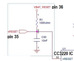
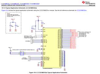
I will show you the problem I am facing with my custom board, this is the Schematic that I have followed.

I have XDS110 Debug Probe

Note: I do not have a LaunchPad

I am using CTI to CM10pin adapter with the following connections

2,4,6,8 pins go to respective JTAG pins;

3,5,9 pins goes to GND;

PIN 1 goes to VDD;

PIN 10 connects to RESET(PIN35) on custom board

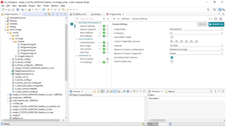
I have imported empty_CC3235S_LAUNCHXL_freertos_ccs project.

In TargetConfig I have selected CC3235S under Board/Device 

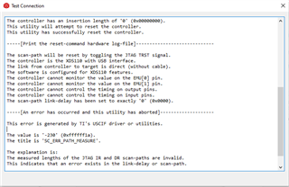
i) SOP MODE - 000(FUNCTIONAL_4WJ) and I get this Error

Note - nRESET(PIN35) goes to GND via 4.7k resistor

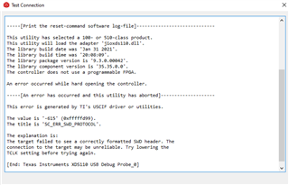
ii) SOP MODE- 001 (FUNCTIONAL_2WJ)

In TargetConfig I have selected CC3235S_SWD under Board/Device 

Note - nRESET(PIN35) goes to GND via 4.7k resistor

QUESTION 1. Is there anything wrong with the connection, if so please let me know? If all connections are correct, does this mean my chip is in Production Mode?

QUESTION 2. Should RESET(PIN35) pin be grounded or pulled up high via VBATT_RESET internally?

iii) SOP MODE-010(UARTLOAD_FUNCTIONAL_4WJ)

Correct me If I am wrong, to program over UART 

I have connected PIN46(TX) and PIN47(RX) of the Module to UARTRX(pin12) and UARTTX(pin11) of the XDS110 Auxiliary Breakout Board Signal respectively. In the Hardware Checklist, they have mentioned PIN 46, PIN 47 for UART FLASHING. Both pins are pulled up high via 100k resistor.

Other pins of the Auxillary Board of XDS110 are as follows: TGTVDD(Sense) - VDD(on custom board) and GND is connected to GND of module.
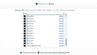
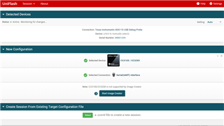
Now, In UNIFLASH

Under Devices, I chose CC3235(BOOTLOADER)

(Note: I do not have a Launchpad)

In Application Image, I uploaded the Programming.sli file created when building the image.syscfg of  empty_CC3235S_LAUNCHXL_freertos_ccs project file

As you can see, all the necessary files are there.

COM Port: XDS Class Application/User UART(COM13)

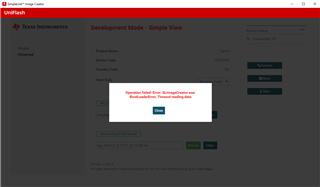
After I load Image, I get the following error
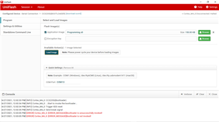
UNIFLASH LOG

[4/27/2021, 12:02:33 PM] [INFO] Cortex_M4_0: CC3235S(Bootloader)
[4/27/2021, 12:02:34 PM] [INFO] Cortex_M4_0: ...Start to invoke the bootloader...
[4/27/2021, 12:02:34 PM] [INFO] Cortex_M4_0: Trigger XDS reset
[4/27/2021, 12:02:35 PM] [INFO] Cortex_M4_0: Send break signal
[4/27/2021, 12:03:05 PM] [ERROR] Cortex_M4_0: [ERROR_MESSAGE]Bootloader is unsuccessfully invoked!
[4/27/2021, 12:03:05 PM] [ERROR] Cortex_M4_0: [ERROR_MESSAGE]Bootloader is not invoked!

This is the error I am getting when using UNIFLASH.

Can anyone please guide me by mentioning the pins I should be using?

A step by step support will be really helpful.

Thanks for your help

Regards

Akshay Bhardwaj

  • Hi Akshay,

    Reading through the info provided, there are a few points to note on your setup which may help resolve your bring up issues.

    1. If you got your CC3235MOD from a reel (and not from taking it off a launchpad EVM), then it will be in production mode. So JTAG access is locked until the device is reflashed with a development mode image through Imagecreator.

    2. I will defer to my HW engineering colleague for this question

    3. In order for the CC3235MOD to be flashable over UART, you need to be in either SOP 100 or SOP 010. So keep your device in SOP 010 during the flashing process, what you currently have is correct. However, the tool you need to use is not the Uniflash tool directly, but rather the Imagecreator tool bundled with Uniflash. Please follow the step-by-step instructions here to setup and use Imagecreator for flashing:

    https://dev.ti.com/tirex/explore/node?node=ABEoqU9o3snoxDcmIpW0EA__fc2e6sr__LATEST

    Since you're using the UART from the XDS110 it should auto-detect your device. Otherwise, you will need to use the CLI version of Imagecreator, where you can specify your COM port manually and not rely on the auto-detect. The full guide for Imagecreator can be found here: https://www.ti.com/lit/swru469

    Regards,

    Michael

  • Hi Michael,

    I did get my CC3235MOD from a reel. So as you are saying, it must definitely be in Production Mode

    As I am using UART from the XDS110 with the following connections: (SOP Mode - 010)

    I have connected PIN46(TX) and PIN47(RX) of the Module to UARTRX(pin12) and UARTTX(pin11) of the XDS110 Auxiliary Breakout Board Signal respectively. In the Hardware Checklist, they have mentioned PIN 46, PIN 47 for UART FLASHING. Both pins are pulled up high via 100k resistor. (Note: nRESET pin PULLED UP HIGH)

    In UNIFLASH, the XDS110 Probe is getting detected but I cannot find CC3235S device when i select it

    So I choose CC31XX/CC32XX as mentioned in the UNIFLASH Imagecreator Basics

    After I follow the steps and upload MCU Img file and Service Pack File Name and try to connect, I get the following error

    Question-1. Is my chip not getting detected or is it something related to the pin connections? Can you please provide me the exact pin-to-pin connection to sort this out?

    Question-2. What should be the state of RESET(pin 35) pin of CC3235MODAS during this process?

    Regards,

    Akshay Bhardwaj

  • Akshay,

    Regarding Question 2:

    There is an internal, 100-kΩ pullup resistor option from the nRESET pin to VBAT_RESET (See image below. Ignore the text "CC3220 IC").

    Note: VBAT_RESET is not connected to VBAT1 or VBAT2 within the module. The following connection schemes are recommended:

    1. Connect nRESET to a switch, external controller, or host, only if nRESET will be in a defined state under all operating conditions. Leave VBAT_RESET unconnected to save power.
    2. If nRESET cannot be in a defined state under all operating conditions, connect VBAT_RESET to the main module power supply (VBAT1 and VBAT2). Due to the internal pullup resistor a leakage current of 3.3 V / 100 kΩ is expected.

    BR,

    Seong