This thread has been locked.

If you have a related question, please click the "Ask a related question" button in the top right corner. The newly created question will be automatically linked to this question.

CC3220SF: How to find (leakage) currents/active peripherals

Part Number: CC3220SF
Other Parts Discussed in Thread: SYSCONFIG, ENERGYTRACE, MSP430FR5969, , SYSBIOS

Dear TI,

I am reducing my current consumption of a CC3220MODASF device in order to increase battery life of a device. I am trying to get the MCU in LPDS mode with NWP idle connected (LSI of 500 ms), which should have typical power consumption of 710 uA according to the documentation. However, for some reason my device does not seem to enter the LPDS mode when it is running in idle loop (I activated the "Enable Policy" in Power SysConfig).

When all my tasks are blocked, I recorded this current consumption with my oscilloscope (1 mV = 1 mA):

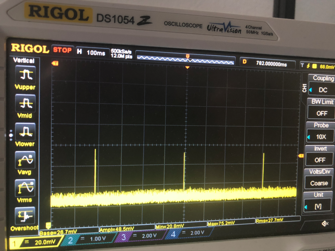
You can see the NWP waking up every 400 ms for the DTIM, but the remaining time the current consumption stays around 27 mA.

My guess is that one of the peripherals or the NWP are blocking the transistion to LPDS mode, however I have no clue which one (I use a Watchdog timer, SPI, I2C, several GPIO etc).
I have tried to disable(or temporarily remove) the peripherals one by one, but unfortunately that is not (easily) doable for my reasonably sized application due to flow dependencies.

I double checked if the MCU was in idle loop during execution by analyzing the CPU execution, and that is correct (all my tasks were blocked).
I have tried deactivating the Watchdog timer (I read there were some issues in the past), but that didn't help.

Therefore I was wondering if there was a way that I could figure out which peripherals are still active. Are there some tools (or tricks) available to check this?
I was checking the XDS110 debugger + Energytrace HDR module, but from my previous experience with Energytrace for MSP430FR5969 I can't remember having this capability.

Best regards,

MJ

  • Hi MJ,

    Are you running the power measurement example? It has a UART interface you can use to set the device to a low power mode and notify you when that mode is entered. 

    Jesu

  • No I was running my custom example. It was just to show that it does not enter LPDS mode in the application..
    I am just ran the power measurement example, and the current shows 5.6 mA in LPDS and Hibernate mode. I have seen this 5.6 mA current passing by at some point in my own application as well (so it has entered LPDS mode for a short while there as well), but for some reason it does not want to enter LPDS at this point and I don't know why.

    So basically I have two problems:

    (1) The LPDS/Hibernate currents are way too high. So I guess that certain (GPIO) ports are leaking current, because the ports are not correctly parked(?)

    (2) My custom application does not want to enter LPDS mode.

    The first problem can be solved using the power measurement example that you mentioned, but the second one I don't know.

  • Ok I might have found the answer for question 1: I double checked the parking of the pins, and found out that a few were incorrect. However, the resulting current did not change for the power measurement configuration and was still 5.6 mA. Then I isolated all the surrounding components, and I figured out that my shorted header (with jumper) for SOP1 to VDD was the reason that it was too high. After removing the shorting jumper the current dropped to the values was expecting: ~4.5uA for hibernate, ~300 uA for LPDS (still have to figure out where the small increase comes from).

    However, question 2 still remains unresolved. The current is now lowered a bit due to the removal of the SOP1 jumper (~20 mA), but the LPDS mode is never entered. I used the RTOS Execution analyzer and temporarily disabled the Power policy in order to analyze the task executions. This was the result:

    As you can see, the idle loop is mostly active. How can I check what is blocking the device?

  • Hi MJ,

    If you don't get the expected current when running the power_measurement example as is this indicates a potential HW issue. Are you using a custom board or LP?

    Jesu

  • Dear Jesu,

    I am using a custom board, but ran both my custom application and the power_measurement example on it.

    The current consumption of the board is (almost) exactly the same as the expected current of the Launch Pad when running the power_measurement example as I mentioned in the previous post. Therefore I don't think it is a hardware issue.

    From the current consumption it seems that the CC3220 stays in active mode (with NWP inactive) with ~20 mA for my custom application. My assumption is that it does not enter the LPDS mode or that some peripherals are forcing the fast clock to remain active. I would like to know if there is some way to check if LPDS is (automatically) activated to get an idea how to fix this.

    MJ

  • MJ,

    If you're even seeing the correct numbers on a Launchpad when running the power measurement examples that suggest something else. May I ask what SDK version and service pack you're using? I just ran the power_measurement example on CC3220SF Launchpad from SDK v3.30 and service pack version sp_3.13.0.3_2.0.0.0_2.2.0.6.bin and was seeing ~130uA.

    Jesu

  • Dear Jesu,

    Unfortunately I broke my 2 LaunchPad boards due to a short-circuit on a connected board during testing a few weeks ago, so I am doing all my tests on my custom boards.

    When I am running the power_measurement example on my custom board with SDK v3.30 and service pack sp_3.13.0.3_2.0.0.0_2.2.0.6 I get current of values jumping between 80 - 150 uA. So it seems that one works fine on the custom PCB. When I don't make a choice, the current consumption is around ~23 mA .

    If I test my custom application on the same board, and I replaced the loop of mainTask() thread with the following code:

    while(1)
    {
        /* Enable LPDS policy */
        Power_enablePolicy();
        Task_Sleep(5000);
    }

    If I execute the application you get the following Execution Analysis which is similar to the one posted above:

    As you can see, the idle loop is mainly active. If I run my custom application:

    Power policy disabled:  ~30 mA
    Power policy enabled: ~20 mA

    As I have said multiple times now; I want to figure out why the current does not drop further.

  • Hi MJ,

    What is the state of your other threads (e.g. blocked, ready...)? Also, what is your PowerCC32XX_config set to? You can find it in ti_drivers_config.c in the Generated Source folder of your project.

    Jesu

  • Dear Jesu,

    Thanks for asking the question. All tasks are blocked except for the idle loop, but when I looked up the PowerCC32XX_config I remember that I setup the GPIO wakeup for LPDS mode. So I started to play around a bit, and this is what happens:

    The PowerCC32XX_config is:

    const PowerCC32XX_ConfigV1 PowerCC32XX_config = {
        .policyInitFxn             = PowerCC32XX_initPolicy,
        .policyFxn                 = PowerCC32XX_sleepPolicy,
        .enterLPDSHookFxn          = NULL,
        .resumeLPDSHookFxn         = NULL,
        .enablePolicy              = true,
        .enableGPIOWakeupLPDS      = true,
        .enableGPIOWakeupShutdown  = false,
        .enableNetworkWakeupLPDS   = true,
        .wakeupGPIOSourceLPDS      = PRCM_LPDS_GPIO4,
        .wakeupGPIOTypeLPDS        = PRCM_LPDS_RISE_EDGE,
        .wakeupGPIOFxnLPDS         = ImuCallback,
        .wakeupGPIOFxnLPDSArg      = 0,
        .wakeupGPIOSourceShutdown  = PRCM_HIB_GPIO13,
        .wakeupGPIOTypeShutdown    = PRCM_HIB_RISE_EDGE,
        .ramRetentionMaskLPDS      = PRCM_SRAM_COL_1|PRCM_SRAM_COL_2|PRCM_SRAM_COL_3|PRCM_SRAM_COL_4,
        .keepDebugActiveDuringLPDS = false,
        .ioRetentionShutdown       = PRCM_IO_RET_GRP_0|PRCM_IO_RET_GRP_1|PRCM_IO_RET_GRP_2|PRCM_IO_RET_GRP_3,
        .pinParkDefs               = parkInfo,
        .numPins                   = 31
    };

    The interrupts of GPIO4 sometimes start a timer (freq = 1Hz), and because of this timer the power consumption remains high.
    However, I want this timer to run on the slow (RTC) clock instead of the 80MHz clock because of its low frequency.

    I configured my timer this way:

        Timer_Params    params;
        Timer_Params_init(&params);
    params.periodUnits = Timer_PERIOD_HZ; params.period = 1; params.timerMode = Timer_CONTINUOUS_CALLBACK; params.timerCallback = timerCallback; activityTimer = Timer_open(Board_TIMER0, &params);

    If I disable the start of the timer, then the current drops to the uA range so the timer is definitely the cause of the problem. I thought this would be done automatically, but how can I force the timer to run on the slow clock (32.768 kHz)?

  • MJ,

    The power management unit has direct control of the slow clock and it cannot be used in application. All general purpose timers use the system clock (80MHz). To make sure I understand, you're saying you have to disable your application timer before going back to sleep to enter LPDS properly?

    Jesu

  • Jesu,

    Yes it is correct that I have to (manually) disable the application timer to enter LPDS properly.
    The problem is that this timer is used to track the time in this state, while it is in LPDS for most of the time.

    I thought the Power Management module would make sure that the slow timers would automatically switch over to the low frequency clock (which it apparently doesn't do). Maybe I am using the 'wrong' timer module for that? Because sometimes it is not very clear to me which timer API I should use:

    - TI Driver Timer (runs on actual Timer modules using the high speed clock directly)

    - ti.sysbios.family.arm.cc32xx.Timer module (according to the docs this module manages the 32Khz RTC timer)

    - ti.sysbios.family.arm.m3.Timer module (uses the SysTick timer)

    I have taken a quick look at all these different timers, but it seems that the API calls are the same or at least very similar. I have not used the SYS/BIOS modules very often, so how do I know which one I am using? And which ones do switch to the low frequency clock if LPDS is active?

  • MJ,

    What exactly do you need the timer for? Keep in mind once you enter LPDS mode state information is lost and only certain MCU registers are retained. If you just need the timer to wake up from sleep you need to use the PRCM APIs. More information in section 15.3 of the TRM.

    Jesu

  • Jesu,

    The GPIO4 port (the one that is configured as wakeup from LPDS) is from an IMU. The IMU generates an interrupt when it starts moving or has stopped for certain amount of time. I use the timer to keep track of the time that has elapsed since a standstill detection (like a stopwatch).

    If I check section 15.3 of the TRM, it seems that the Slow Clock Counter could help me out if I store the value of the counter manually, and then convert it to seconds manually as well. I will try to implement this on Monday.

    MJ

  • Jesu,

    I rewrote the code slightly to use the Slock Clock counter, and it worked like I thought.
    Now there are no active timers running, and LPDS mode is entered correctly.
    I am still able to retrieve the time that has passed on a polling basis (which is fine, because I am waking up for other tasks already).
    Thank you for the help!

    MJ